Gas sensor

a gas sensor and sensor output technology, applied in the field of gas sensors, can solve the problems of difficult stable measurement, lower measurement accuracy, and drawbacks of the lamininate-type gas sensor, and achieve the effects of suppressing oscillation, suppressing oscillation, and suppressing oscillation

Active Publication Date: 2013-02-07
NGK SPARK PLUG CO LTD
View PDF5 Cites 22 Cited by
  • Summary
  • Abstract
  • Description
  • Claims
  • Application Information

AI Technical Summary

Benefits of technology

[0014]According to the above gas sensor (1) of the invention, since the two cells electrically communicate with each other through the leakage portion, a delay (phase delay) in change in the output voltage of the oxygen-concentration detection cell in relation to a change in the current of the oxygen pump cell is reduced. Accordingly, it is possible to suppress the occurrence of oscillation in feedback control performed by a control circuit which controls the current of the oxygen pump cell in accordance with a change in the output voltage of the oxygen-concentration detection cell. That is, when the pump current of the oxygen pump cell is changed, the above configuration prevents the output voltage of the oxygen-concentration detection cell from being greatly influenced, whereby fluctuation of the sensor output is suppressed. Notably, as used herein, the expression “electrically communicate” means that a path exists through which electrons and / or ions move.
[0015]Further, since the leakage portion is provided in the gas sensor, it is possible to suppress oscillation without preparing a dedicated control circuit which includes a constituent element for suppressing oscillation stemming from feedback control, such as a high pass filter including a resistor and a capacitor. Accordingly, it is possible to insure compatibility of the control circuit with a gas sensor which does not cause the control circuit to oscillate and which does not require a dedicated control circuit. In addition, since constituent elements, such as a resistor and a capacitor, for suppressing oscillation are not additionally provided in the control circuit, the manufacturing cost can be reduced.
[0016]Incidentally, in the above-described gas sensor (1) of the invention, the insulating layer, which insulates the oxygen-concentration detection cell and the oxygen pump cell from each other, is interposed between the oxygen-concentration detection cell and the oxygen pump cell. Further, the leakage portion, which electrically connects the oxygen-concentration detection cell and the oxygen pump cell, is provided separately from the insulating layer. Oscillation in feedback control can be suppressed by establishing electrical communication between the two cells. Therefore, the gas sensor may be configured such that electrical communication is established between the oxygen-concentration detection cell and the oxygen pump cell by interposing an electrical connection layer between the two cells without providing the insulating layer therebetween. However, if such a connection layer is provided, a large voltage (also referred to as “leakage voltage”) is produced due to a current (also referred to as “leakage current”) flowing between the two cells via the connection layer and is superimposed on the output voltage of the oxygen-concentration detection cell. As a result, the measurement accuracy of the gas sensor may decrease. In contrast, the gas sensor (1) of the invention is configured such that the insulating layer is interposed between the oxygen-concentration detection cell and the oxygen pump cell and the leakage portion is separately provided at a portion of the insulating layer. Therefore, superposition of a leakage voltage on the output voltage of the oxygen-concentration detection cell can be adequately suppressed. Accordingly, it is possible to suppress oscillation in feedback control, while preventing a decrease in measurement accuracy of the gas sensor due to the leakage current.

Problems solved by technology

However, such a laminate-type gas sensor has a drawback.
When the time lag becomes excessively large, the control circuit oscillates and the sensor output fluctuates, which makes stable measurement difficult and lowers measurement accuracy.
However, the use of such a dedicated control circuit may impair compatibility of the control circuit with a gas sensor of a type which does not cause the control circuit to oscillate and which avoids the necessity of providing a high pass filter in the control circuit.
Also, since a resistor and a capacitor must be added in order to provide a high pass filter in the control circuit, the manufacturing cost may thereby increase.

Method used


Image

  • Gas sensor
  • Gas sensor
  • Gas sensor

Examples


first exemplary embodiment

A. First Exemplary Embodiment

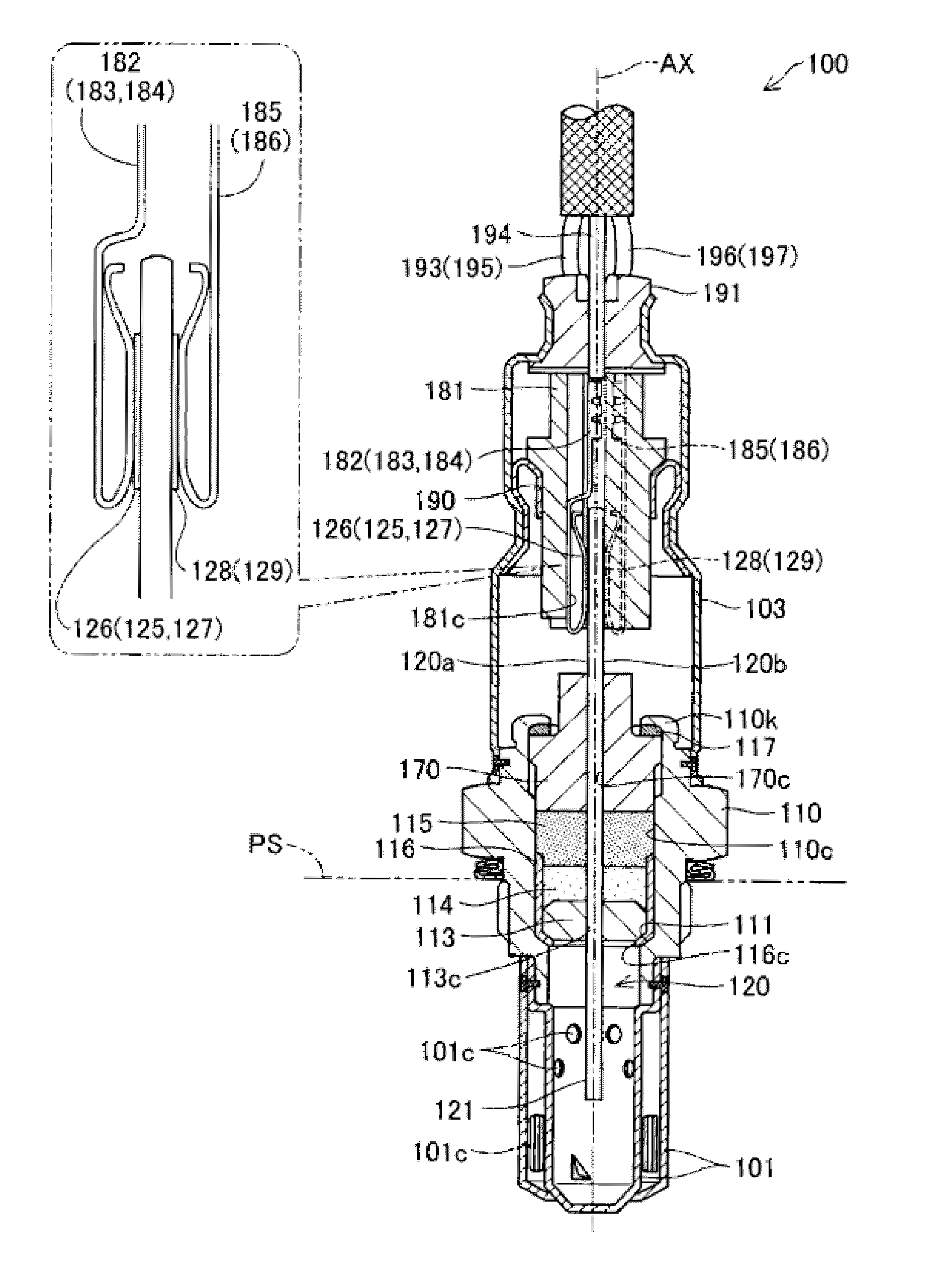
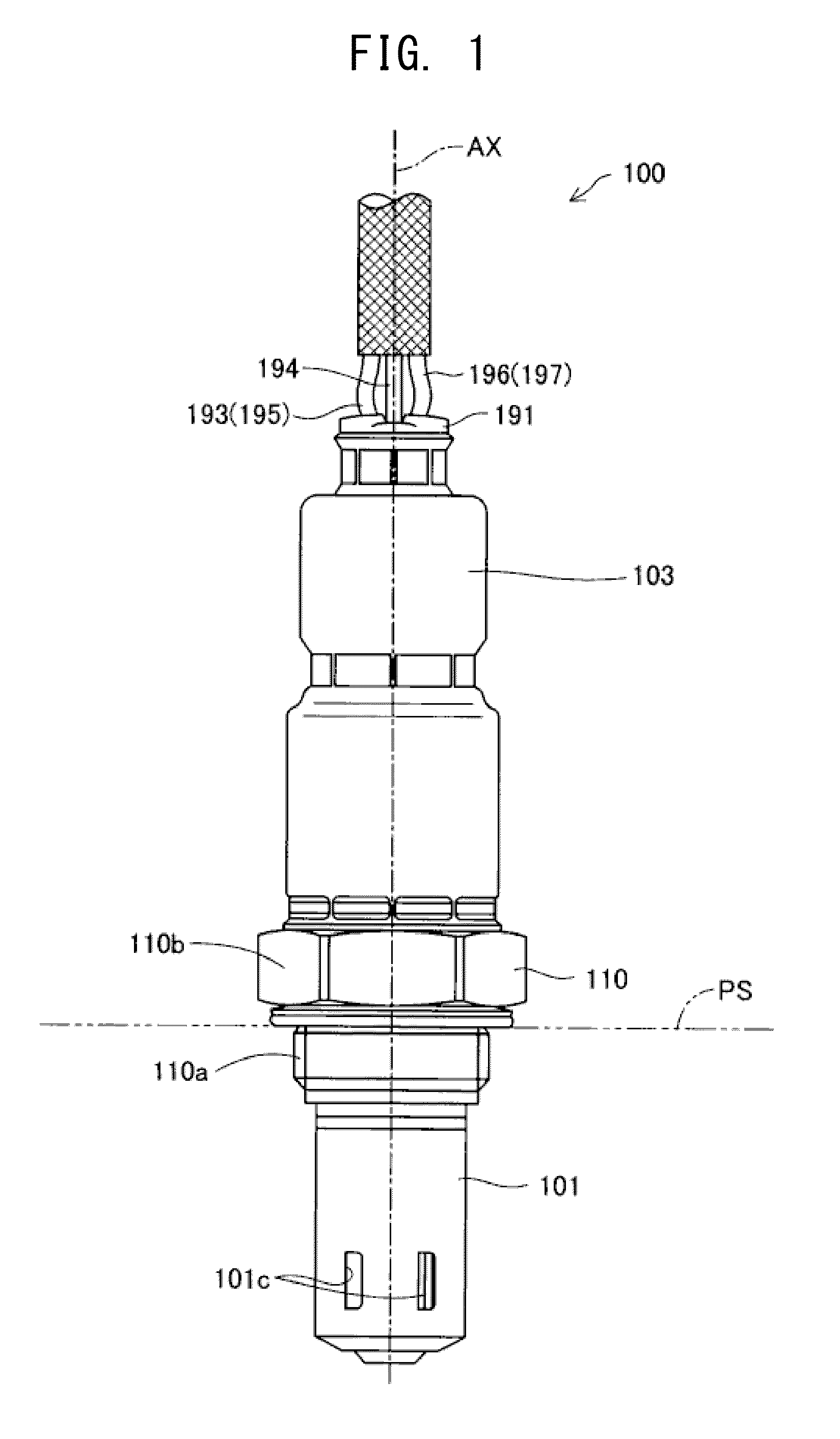
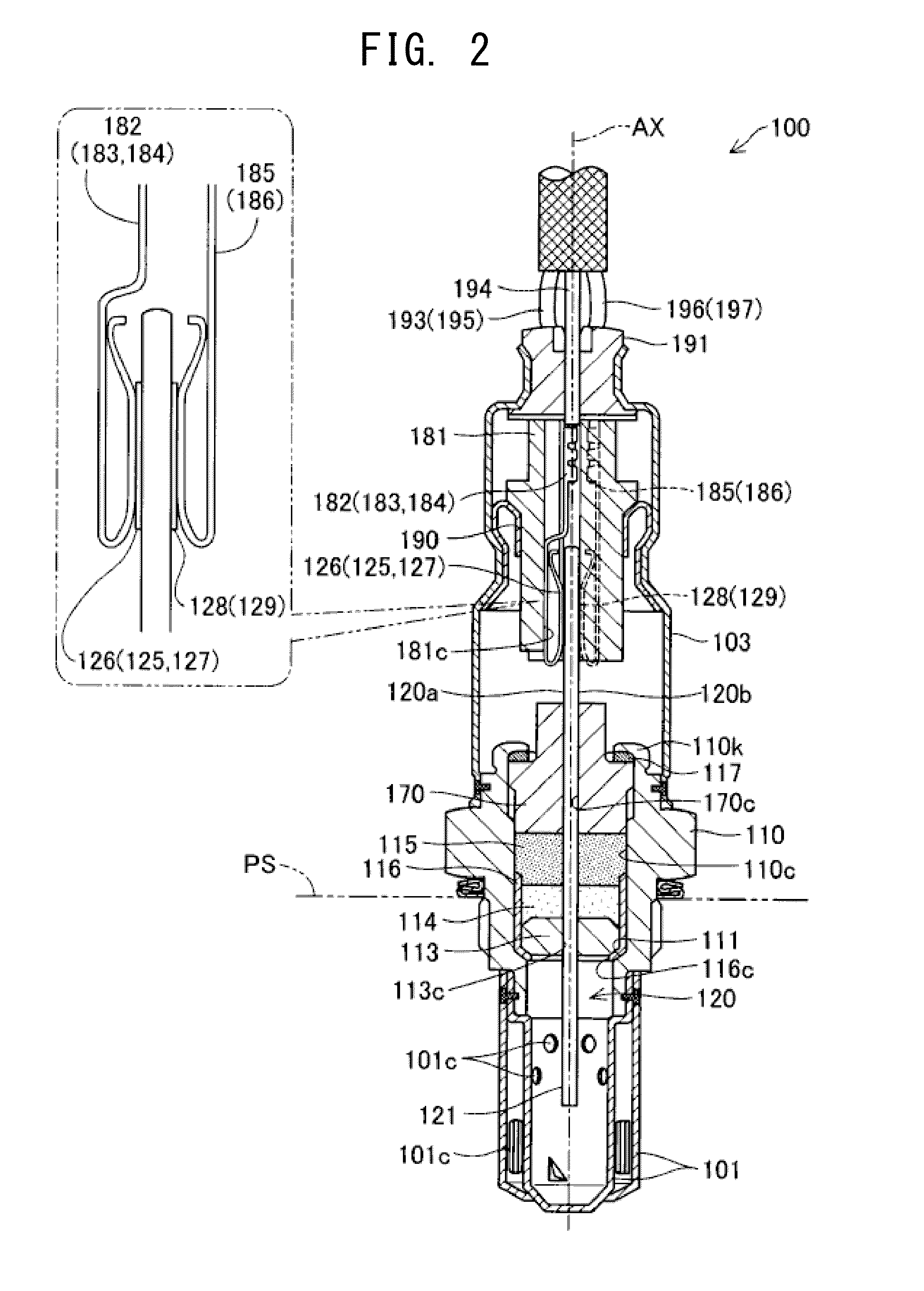
[0110]FIG. 1 is a schematic view showing the external view of a gas sensor 100 according to one embodiment of the present invention. In FIG. 1, the imaginary center axis AX of the gas sensor 100 (hereinafter also referred to as the “axis AX”) is shown by an alternate long and short dashed line. This gas sensor 100 is a so-called full range air-fuel-ratio sensor which is attached to an exhaust pipe of an internal combustion engine or the like and linearly detects the concentration of oxygen contained in exhaust gas (gas to be measured) over a full range ranging from a rich region to a lean region.

[0111]The gas sensor 100 extends in the direction of the axis AX. The gas sensor 100 is fixedly attached to the outer surface of the exhaust pipe such that a front end portion (a lower end portion in FIG. 1) of the gas sensor 100 is inserted into the exhaust pipe, and a rear end portion (an upper end portion in FIG. 1) thereof projects outward from the exhaust pi...

second exemplary embodiment

B. Second Exemplary Embodiment

[0181]FIG. 10 is a schematic view used for describing the structure of a gas sensor 100B which is another structural example of the gas sensor of the present invention. FIG. 10 is substantially the same as FIG. 5 except that the alumina layers 139 and 154 are omitted from the oxygen pump cell 135 and the oxygen-concentration detection cell 150 and that the leakage portion 148 is formed at a position different from the position of the leakage portion 148 in FIG. 5. In the gas sensor 100B of this structural example, the alumina layer 139 is eliminated from the oxygen pump cell 135, and the solid electrolyte member 136 of the oxygen pump cell 135 is formed as a platelike member having a size similar to that of the spacer 145. Similarly, the alumina layer 154 is eliminated from the oxygen-concentration detection cell 150, and the solid electrolyte member 151 of the oxygen-concentration detection cell 150 is formed as a platelike member having a size similar...

modification 1

C1. Modification 1

[0184]In the gas sensor 100 of the above-described embodiment, the leakage portion 148 is formed in a region which overlaps the heating resistor 163 of the heater element 160 when the gas sensor element 120 is viewed in the lamination direction. The leakage portion 148 may also be provided outside that region. However, forming the leakage portion 148 in such a region is preferred, because the temperature of the leakage portion 148 can be adequately controlled. Notably, the leakage portion 148 may be provided in a region near the heating resistor 163 which can be heated by the heating resistor 163.


PUM

PropertyMeasurementUnit
concentrationaaaaaaaaaa
areaaaaaaaaaaa
output voltageaaaaaaaaaa

Abstract

A gas sensor (100) includes an oxygen pump cell (135) and an oxygen-concentration detection cell (150) laminated together with a spacer (145) interposed therebetween. The spacer (145) has a gas detection chamber (145c) which faces electrodes (137, 152) of the cells (135, 150). The oxygen-concentration detection cell (150) produces an output voltage corresponding to the concentration of oxygen in the gas detection chamber (145c). The oxygen pump cell (135) pumps oxygen into and out of the measurement chamber (145c) such that the output voltage of the oxygen-concentration detection cell (150) becomes equal to a predetermined target voltage. A leakage portion mainly formed of zirconia is disposed between which electrically connects the oxygen-concentration detection cell (150) and the oxygen pump cell (135).

Description

BACKGROUND OF THE INVENTION[0001]1. Field of the Invention[0002]The present invention relates to a gas sensor.[0003]2. Description of Related Art[0004]An example of known gas sensors for detecting a specific gas is an oxygen sensor which includes a cell having a pair of electrodes disposed on the outer surface of a solid electrolyte member and which measures the air-fuel ratio of air-fuel mixture supplied to an internal combustion engine (hereinafter referred to as the air-fuel ratio of the internal combustion engine). Particularly, a laminate-type gas sensor is known in which two cells are stacked or laminated with a measurement chamber formed therebetween, and which is adapted to detect the concentration of oxygen contained in exhaust gas over the full range of the air-fuel ratio of the internal combustion engine (see Patent Document 1 below, etc.). In the laminate-type gas sensor, a first cell (also called an “oxygen-concentration detection cell”) outputs to an external control c...

Claims


Application Information

Patent Timeline
Patent Type & Authority Applications(United States)
IPC IPC(8): G01N27/409
CPCG01N27/406G01N27/4062G01N27/41G01N27/409G01N27/419G01N27/407
Inventor ITO, TETSUYATERAMOTO, SATOSHIMORI, KENTARO
Owner NGK SPARK PLUG CO LTD
Why Eureka
Try Eureka