
Denitrification process for remediation of contaminated groundwater and soil

a technology of nitrate and groundwater, applied in the direction of multi-stage water/sewage treatment, water/sludge/sewage treatment, chemistry apparatus and processes, etc., can solve the health risk of humans or local ecological systems, hinder the utility of groundwater remediation projects, and inability to apply and distribute sufficient quantities of nitrate in groundwater without. , to achieve the effect of facilitating the creation of anaerobic conditions and enhancing the degradation of residual nitra

Inactive Publication Date: 2013-02-07
WILSON SCOTT B +1
View PDF3 Cites 3 Cited by
  • Summary
  • Abstract
  • Description
  • Claims
  • Application Information

AI Technical Summary

Benefits of technology

The patent describes a method of remedying soil contamination with nitrates using a secondary carbon source. This source is introduced around the contamination area to contain the nitrates and promote their degradation. The secondary carbon source works by creating anaerobic conditions that destroy the nitrates. The method ensures effective remediation of the contaminated soil.

Problems solved by technology

This contamination is often the result of accidental release of fuels (e.g. gasoline or diesel fuel) from storage, transport, or transfer devices including but not limited to storage tanks, pipelines, dispenser pumps, rail cars, and tank trucks.
This petroleum contamination often presents a health risk to humans or local ecological systems, therefore it is desirable to destroy or remove the contamination.
Although nitrate is a low-cost, soluble amendment that is easily applied to groundwater, the inherent toxicity of nitrate is generally a problem hindering its utility for groundwater remediation projects.
The U.S. government regulates that nitrate should not exist in concentrations higher than 10 mg / L (as nitrogen), and it is impractical and inefficient to apply and distribute sufficient quantities of nitrate in groundwater without exceeding this concentration threshold.

Method used


Image

  • Denitrification process for remediation of contaminated groundwater and soil
  • Denitrification process for remediation of contaminated groundwater and soil
  • Denitrification process for remediation of contaminated groundwater and soil

Examples


Embodiment Construction

[0019]The detailed description set forth below is intended as a description of the presently preferred embodiment of the invention, and is not intended to represent the only form in which the present invention may be constructed or utilized. The description sets forth the functions and sequences of steps for constructing and operating the invention. It is to be understood, however, that the same or equivalent functions and sequences may be accomplished by different embodiments and that they are also intended to be encompassed within the scope of the invention.

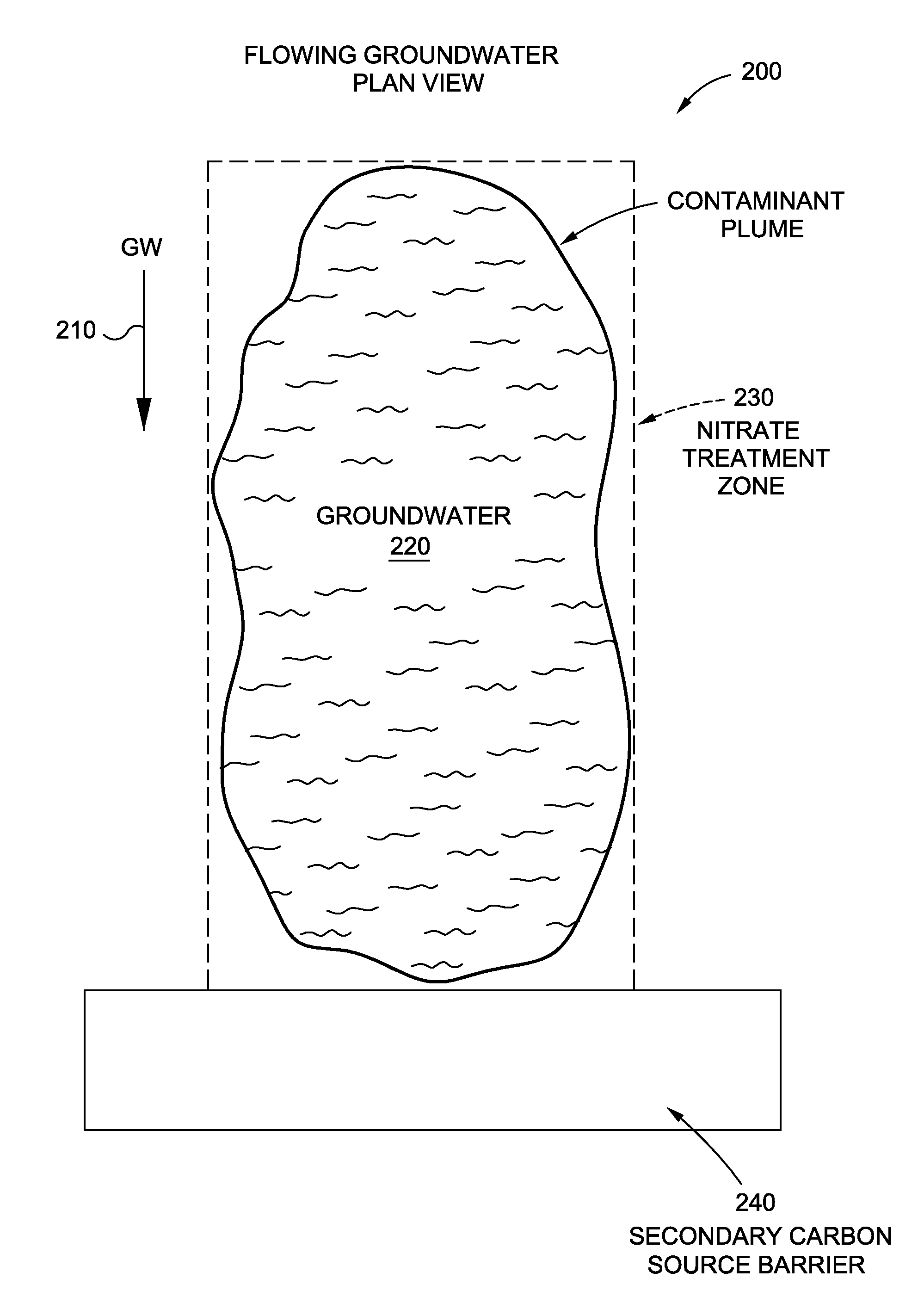
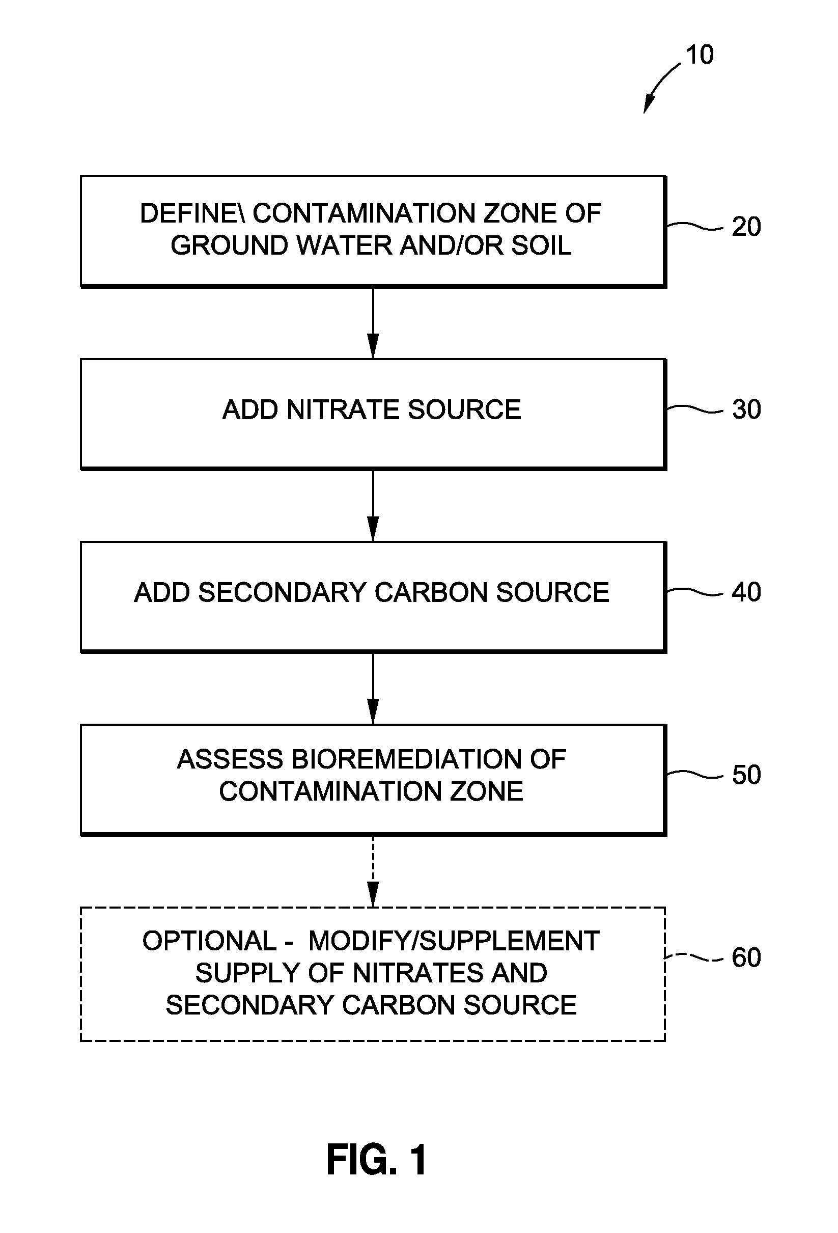
[0020]Referring now to FIG. 1, there is shown a diagram of the steps for performing the processes of the present invention according to a preferred embodiment. As illustrated, the process 10 comprises the initial step 20 of defining a contamination zone of soil and / or groundwater sought to be treated by the processes of the present invention. In this regard, such zone will be defined by an area, thickness and depth of soil and / ...


PUM


Abstract

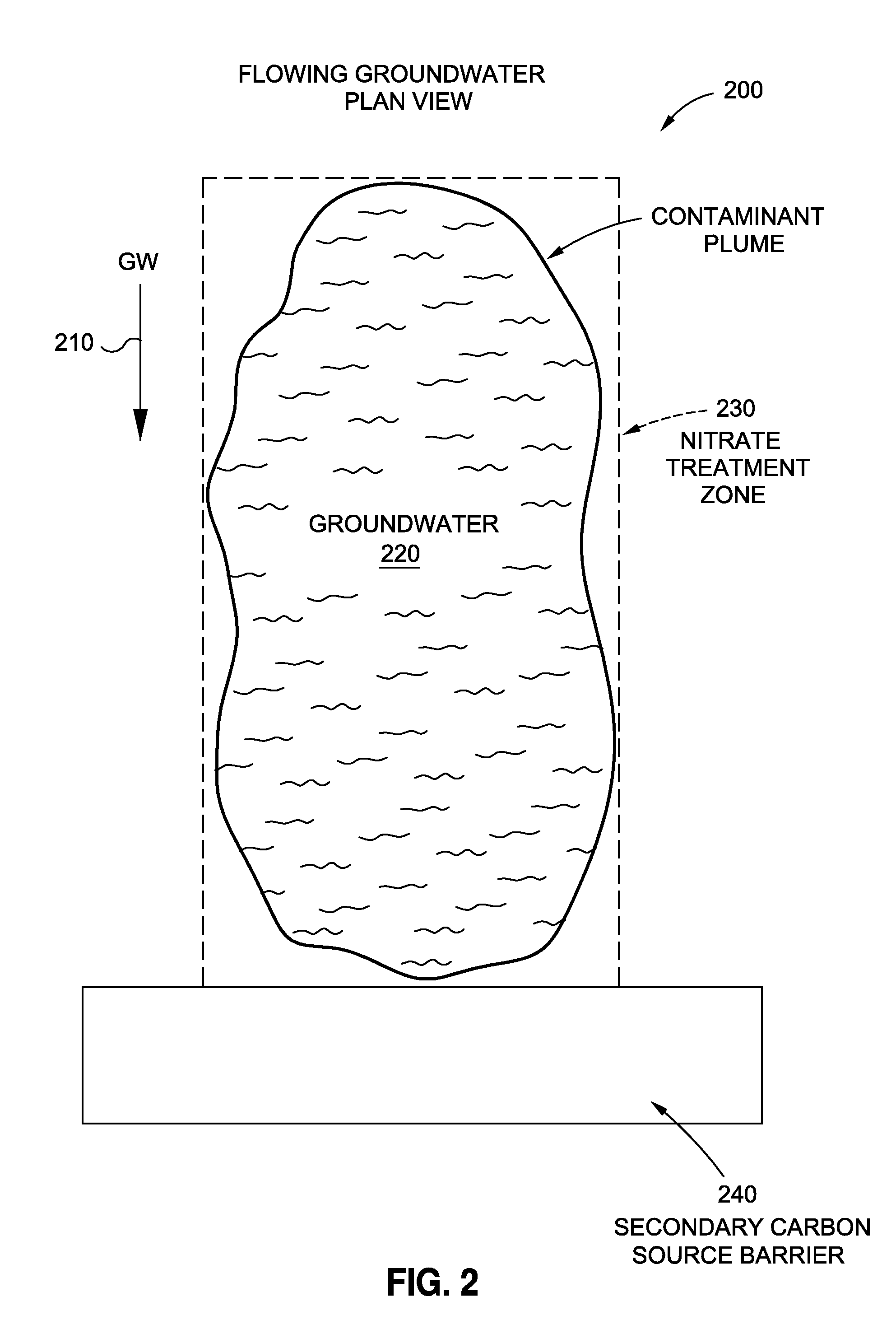
Processes for removing hydrocarbon contaminants from soil and groundwater via enhanced biological denitrification. A contamination zone of groundwater and / or soil is identified to define a volume or zone of contaminants to be treated. A source of nitrate is applied to the contaminant zone to serve as an electronic acceptor for enhanced bioremediation of the petroleum hydrocarbons. A further carbon source, secondary to the primary contaminant hydrocarbons, is added to form a barrier about the nitrate treatment zone to stimulate degradation of any nitrate migrating from the treatment zone. A further carbon source is also added to stimulate the degradation of any residual nitrate once the primary carbon source of the contaminant hydrocarbons have been destroyed.

Description

CROSS-REFERENCE TO RELATED APPLICATIONS[0001]The present application claims priority to U.S. Provisional Patent Application Ser. No. 61 / 514,131, entitled DENITRIFICATION PROCESS FOR REMEDIATION OF CONTAMINATED GROUNDWATER AND SOIL, filed Aug. 2, 2011.STATEMENT RE: FEDERALLY SPONSORED RESEARCH / DEVELOPMENT[0002]Not ApplicableBACKGROUND[0003]Hydrocarbon contamination exists in groundwater and soil at thousands of sites around the world. This contamination is often the result of accidental release of fuels (e.g. gasoline or diesel fuel) from storage, transport, or transfer devices including but not limited to storage tanks, pipelines, dispenser pumps, rail cars, and tank trucks. This petroleum contamination often presents a health risk to humans or local ecological systems, therefore it is desirable to destroy or remove the contamination.[0004]Groundwater is a valuable natural resource due to its use as drinking water in many areas, as well as its importance in ecology and natural water...

Claims


Application Information

Patent Timeline
IPC IPC(8): B09C1/08C02F9/04C02F9/14
CPCB09C1/08C02F2103/06C02F3/306
Inventor WILSON, SCOTT B.MORK, BENJAMIN V.
Owner WILSON SCOTT B
Learn More