Interlaminer reinforced composite structures

a technology of reinforced composites and interlocking, which is applied in the direction of paper/cardboard containers, ceramic layered products, transportation and packaging, etc., can solve the problems of composite failure, composite strength reduction, composite failure, etc., and achieve the effect of promoting mechanical interlocking

a technology of reinforced composites and interlocking, which is applied in the direction of paper/cardboard containers, ceramic layered products, transportation and packaging, etc., can solve the problems of composite failure, composite strength reduction, composite failure, etc., and achieve the effect of promoting mechanical interlocking

US20130034724A1Active Publication Date: 2013-02-07SODANO HENRY

Image

  • Interlaminer reinforced composite structures
  • Interlaminer reinforced composite structures
  • Interlaminer reinforced composite structures

Examples


Embodiment Construction

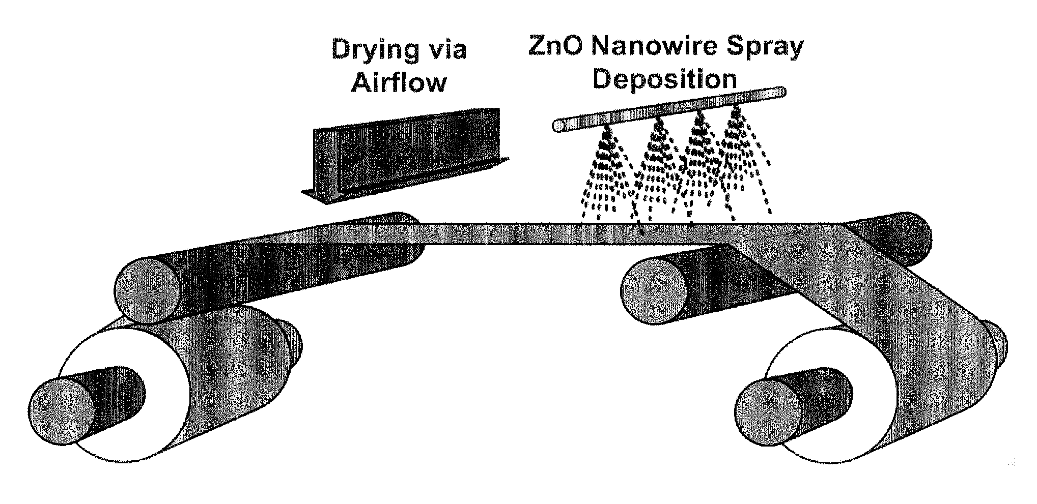
[0023]Embodiments of the invention are directed to interlaminar reinforced laminar composites that include a dispersion of nanowires, or other low-dimensional nanoparticles, at the interface of at least two adjacent laminae of the laminar composite where one or more binding agents binds the nanowires to the resin of adjacent laminae at their interface. The nanowires improve the interlaminar strength while maintaining the composite's in-plane properties. In embodiments of the invention, laminar composites having interlaminar reinforcement are formed by the deposition of nanowires on a lamina surface. In embodiments of the invention, the nanowires have been treated with a binding agent that is chosen to bind to the nanowire surface with the polymer matrix of the composite during cure of the thermosetting resin when forming the continuous matrix of the composite. Treatment by the binding agent results in binding that is chemical or physical in nature. For example, binding can be by cov...


PUM

PropertyMeasurementUnit
Thicknessaaaaaaaaaa
Thicknessaaaaaaaaaa
Diameteraaaaaaaaaa

Abstract

In an embodiment of the invention, a laminar composite has at least one interlaminar reinforced interface comprising a dispersion of binding-agent-treated low-dimensional nanoparticles with a large aspect ratio fixed between adjacent lamina by residues of the binding agents. In another embodiment of the invention, a method to prepare a laminar composite having reinforced interfaces involves the deposition of binding-agent-treated low-dimensional nanoparticles from a solution or suspension onto the surface or a prepreg sheet, where, optionally, after removal of the liquid that comprises the solution or suspension, sheets of the prepreg are layed-up and cured to form the laminar composite.

Description

BACKGROUND OF THE INVENTION[0001]The need for materials that display high specific strength, stiffness, and toughness in excess of those displayed by single phase engineering materials has resulted in the development of composites derived from two or more non-homogeneous materials, where a reinforcing material, generally of greater strength and / or stiffness, is dispersed within a continuous bulk matrix material. Composites allow the properties of the bulk material to be tailored for a specific application. A very useful type of composite is a laminar composite with pluralities of laminae, where each lamina contains unidirectional or woven reinforcing fibers, which are combined to form a composite. The orientation of the fibers can differ from one lamina to another in a stack of laminae. The reinforcement is predominately in the direction of the reinforcing fibers in the laminae, in-plane, with little or no reinforcement to the common perpendicular to the fibers, the thickness of the...

Claims


Application Information

Patent Timeline
07 Feb 2013
Publication
US20130034724A1
IPC
B32B5/02; B32B37/14; B32B7/04; B32B37/02; B32B37/12; B82Y30/00
CPC
B32B7/04; Y10T156/10; B32B37/02; B32B37/12; B32B37/14; B29C70/28; B82Y30/00; B32B2305/076
Inventors
SODANO, HENRY