Fixture for Drilling Vias in Back-Contact Solar Cells

Inactive Publication Date: 2013-02-14
APPLIED MATERIALS INC
View PDF18 Cites 4 Cited by
  • Summary
  • Abstract
  • Description
  • Claims
  • Application Information

AI Technical Summary

Benefits of technology

[0013]In some embodiments, the ceramic material comprises alumina. In detailed embodiments, the ceramic material has a melting point that minimizes

Problems solved by technology

An issue for any back-contact silicon solar cell is developing a low-cost process sequence that also electrically isolates the negative and positive polarity grids and junctions.
The technical issu

Method used


Image

  • Fixture for Drilling Vias in Back-Contact Solar Cells
  • Fixture for Drilling Vias in Back-Contact Solar Cells
  • Fixture for Drilling Vias in Back-Contact Solar Cells

Examples


Example

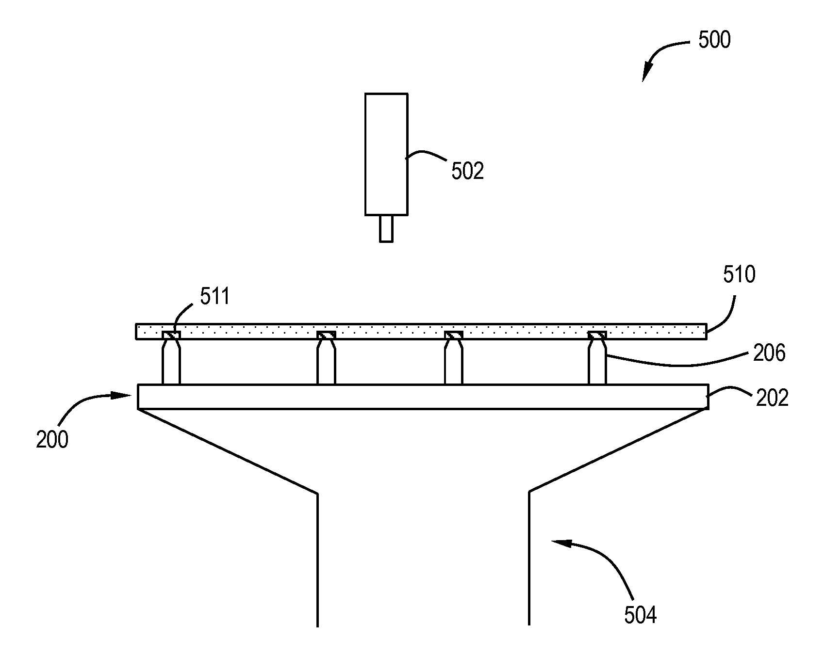
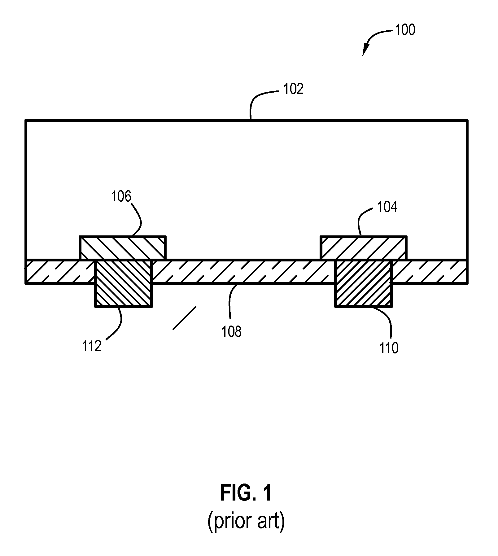
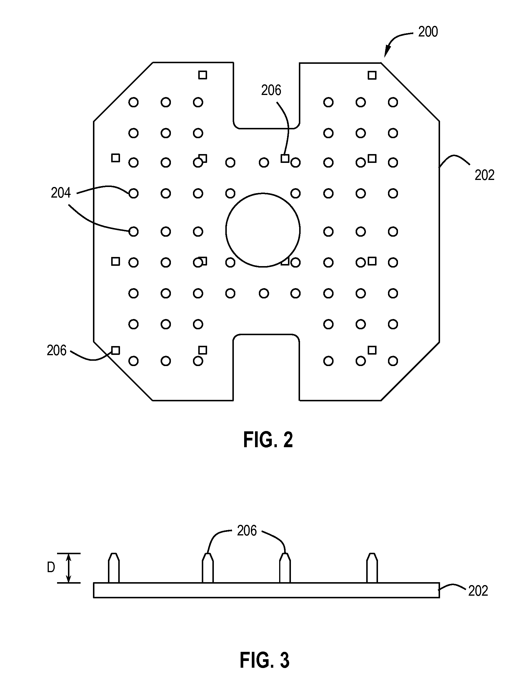
[0026]The emitter-wrap-through (EWT) silicon solar cell is a back-contact solar cell without any grids on the front surface. Instead of busbars, the EWT solar cell has many printed silver bondpad areas on the rear surface that will be the contact points with the module backsheet. The fabrication of an EWT cell uses a laser to drill holes in the silicon substrate. The emitter (n+ junction on the surface of the p-type Si substrate) is diffused on the front surface, rear surface, and on the surfaces inside the holes—thereby forming a conductive channel (“via”) from the front surface to the rear surface to enable the back-contact cell design. The emitter has limited conductivity, with typical values between 30 and 150 ohms / square. A high density of vias (typically between 0.5 and 5 holes per mm2) is therefore necessary to limit the resistance losses due to current flow in the front emitter and in the vias. A 156-mm by 156-mm EWT Si solar cell may require up to 120,000 holes. Creating a ...


PUM

PropertyMeasurementUnit
Distanceaaaaaaaaaa
Distanceaaaaaaaaaa
Electrical resistanceaaaaaaaaaa

Abstract

Methods and systems for manufacturing back contact solar cells that have improved efficiency and device electrical properties. the solar cell device described herein includes an Emitter Wrap Through (EWT) solar cell that has plurality of laser drilled vias disposed in a spaced apart relationship to metal gridlines formed on a surface of the substrate. Solar cell structures that may benefit from the invention disclosed herein include back-contact solar cells, such as those in which both positive and negative contacts are formed only on the rear surface of the device.

Description

BACKGROUND[0001]Embodiments of the present invention generally relate to apparatus and methods for making back-contact silicon solar cells and solar cells made by such methods. More specifically, embodiments of the invention are directed to fixtures for laser drilling back-contact solar cells and methods use.[0002]The solar cell design in widespread use today has a p / n junction formed near the front surface (that surface which receives the light) which creates an electron flow as light energy is absorbed in the cell. The conventional cell design has one set of electrical contacts on the front side of the cell, and a second set of electrical contacts on the back side of the solar cell. In a typical photovoltaic module these individual solar cells are interconnected electrically in series to increase the voltage. This interconnection is typically accomplished by soldering a conductive ribbon from the front side of one solar cell to the back side of an adjacent solar cell.[0003]Back-co...

Claims


Application Information

Patent Timeline
IPC IPC(8): B23K26/38B23Q3/00B25B11/00
CPCB23K26/382B23K26/40B23K37/0408B23K2101/40B23K2103/50B23K2103/52H01L31/022458H01L31/0682H01L31/1804Y02E10/547Y02P70/50
Inventor FRANKLIN, JEFFREY L.GEE, JAMES M.
Owner APPLIED MATERIALS INC
Why Eureka
Try Eureka