
Method and apparatus for friction stir welding tube ends for a heat exchanger

a technology of friction stir welding and heat exchanger, which is applied in the direction of soldering apparatus, lighting and heating apparatus,auxillary welding devices, etc., can solve the problems of increased corrosion susceptibility of fusion welding joints, high labor costs to prepare and weld all tube joints, and defect repair costs, so as to eliminate significant costs, improve performance, and eliminate or reduce long-term corrosion related failures

Active Publication Date: 2013-02-14
LOCKHEED MARTIN CORP
View PDF5 Cites 30 Cited by
  • Summary
  • Abstract
  • Description
  • Claims
  • Application Information

AI Technical Summary

Benefits of technology

The invention introduces a new method for joining tubes to tubessheets in a heat exchanger that replaces the traditional fusion weld process. This solid state weld joint, also known as friction stir weld (FSW), utilizes the same or similar materials for the tubes and tubessheets, resulting in a weld with improved performance and reduced costs. By eliminating long-term corrosion-related failures, the invention significantly increases the efficiency and reliability of heat exchangers.

Problems solved by technology

The process of welding the heat exchanger tubes has many drawbacks including: (1) high labor costs to prepare and weld all of the tube joints via manual fusion welding techniques, (2) defect repair costs due to the complex manual or semi-automatic fusion welding process, and (3) increased corrosion susceptibility of the fusion welding joint.
Corrosion is a major cause of working fluid contamination, especially where one of the systems is corrosive.

Method used


Image

  • Method and apparatus for friction stir welding tube ends for a heat exchanger
  • Method and apparatus for friction stir welding tube ends for a heat exchanger
  • Method and apparatus for friction stir welding tube ends for a heat exchanger

Examples


Embodiment Construction

[0028]FIG. 15 is a schematic diagram of the Rankine cycle 900. The cycle shown includes a pump 910, a boiler 920 a turbine 930 and a condenser 940. The condenser 940 includes a heat exchanger which uses a cooler fluid to remove heat from a gas after it has passed through the turbine 930. The cooler fluid can be corrosive. The gas may also be corrosive. So the heat exchanger associated with the condenser 940, in certain applications, operates in a corrosive environment. A heat exchanger can be formed in different ways. One from of heat exchanger includes multiple tubes placed between two tubesheets and encapsulated in a pressure vessel shell. The heat exchanger, therefore, includes one or more joints formed between a tube and a tube sheet. It should be understood that a heat exchanger is one application for the apparatus and method described herein and that there are other possible applications for the apparatus and method described herein.

[0029]Friction stir welding (FSW) is a solid...


PUM


Abstract

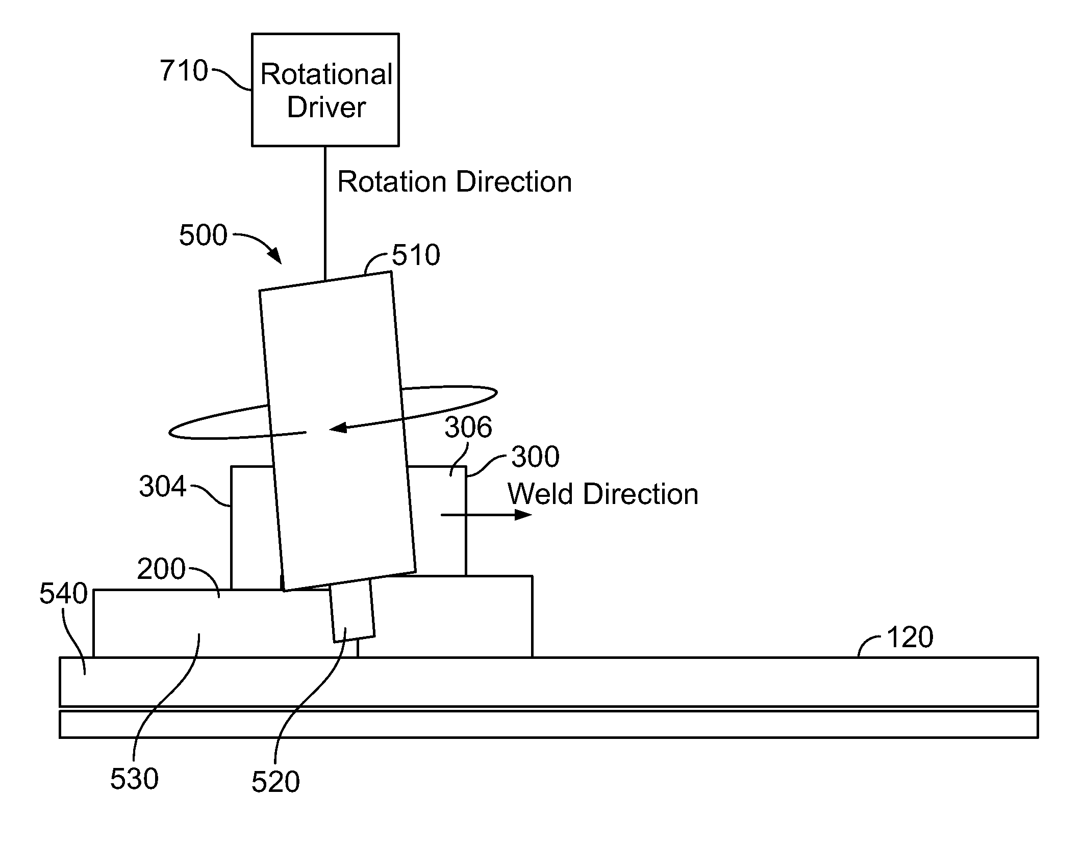
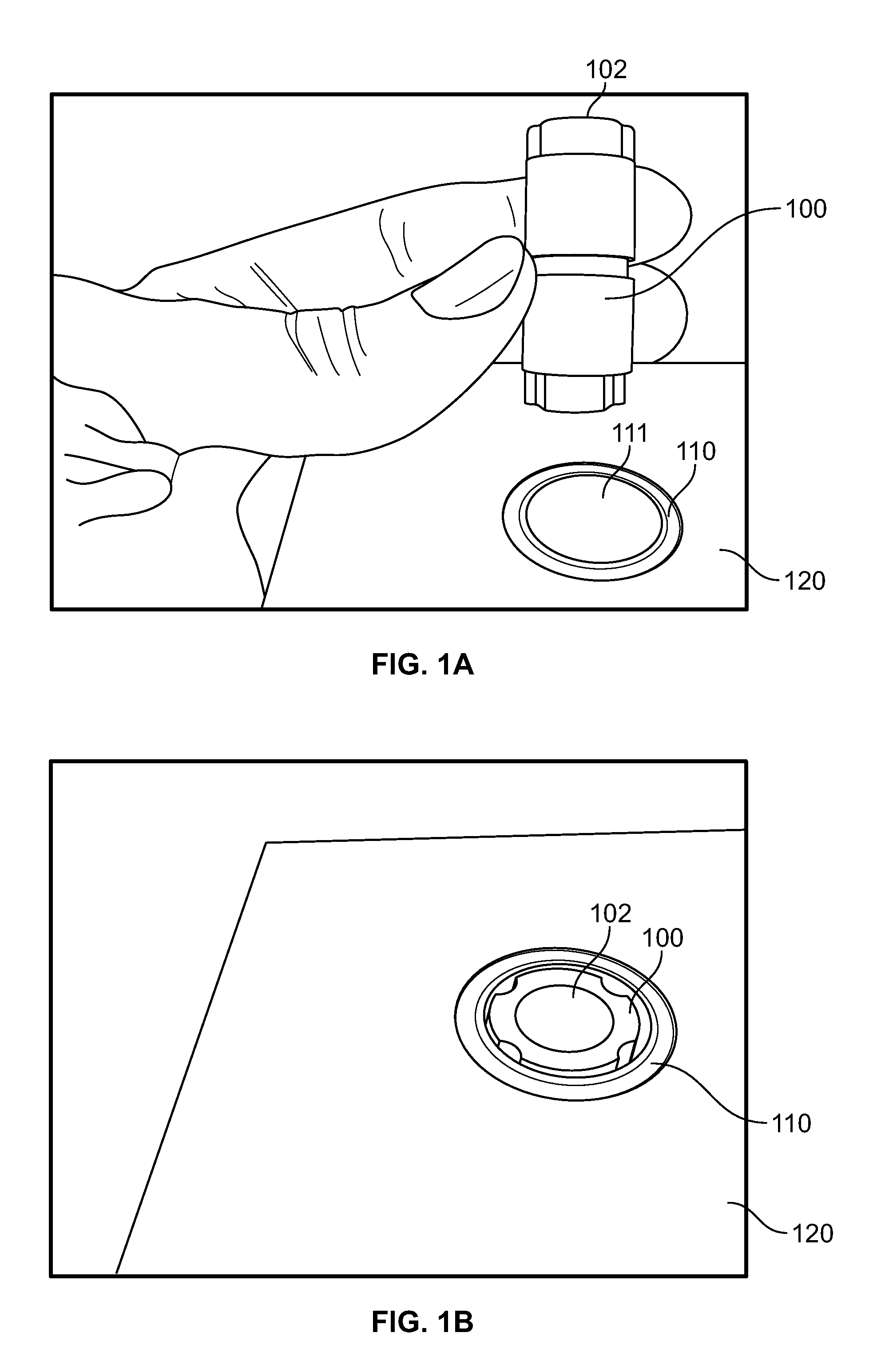
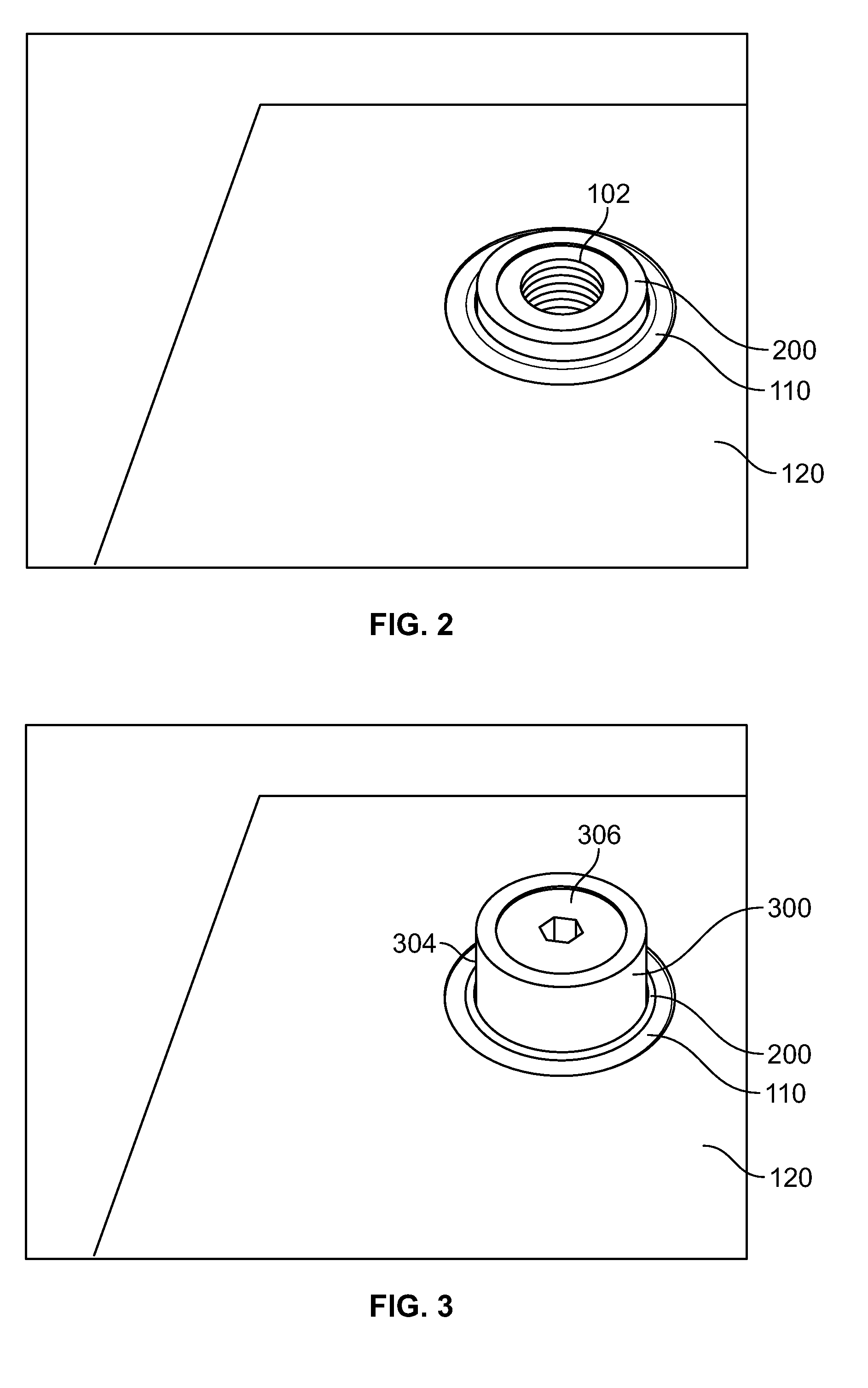
A method for forming a joint between a tube and a sheet includes forming an anvil at least within the tube, and welding the tube to the sheet in the presence of the anvil. The anvil includes an anchor which is placed within the tube near or at the joint to be formed. At least one washer is placed over the end of the anchor that is near the joint to be formed. A threaded fastener is then placed into the anchor to securely hold the anchor within the tube and to provide a backing substantial enough so that a friction stir weld can be formed. The threaded fastener and the washer can be used as a guide for the friction stir weld. Once the weld is completed, the anvil can be removed. The weld can be further processed to remove burrs and other material.

Description

RELATED APPLICATIONS[0001]This application claims the benefit under 35 U.S.C. §119(e) of prior U.S. Provisional Patent Application No. 61 / 521,589 filed Aug. 9, 2011, which is incorporated herein by reference.TECHNICAL FIELD[0002]Various embodiments described herein relate to a method and an apparatus for friction stir welding the tube ends of tubes in a heat exchanger to a tubesheet in a pressure vessel.BACKGROUND[0003]Common industrial heat exchangers include multiple tubes placed between two tubesheets and encapsulated in a pressure vessel shell. Fluids or gasses of differing temperatures are passed through the heat exchanger, transferring the heat energy from one medium to the other. The tubes may be press fit or welded in place. Where the separation of the liquids or gasses is critical, as in nuclear heat exchangers and chemical plants, the tubes must be welded in place and checked for leaks prior to entering service. The process of welding the heat exchanger tubes has many draw...

Claims


Application Information

Patent Timeline
IPC IPC(8): B23K20/12
CPCB23K37/0536B23K20/126F28D7/16F28F9/18F28F2275/062B23K20/129
Inventor ELLER, MICHAEL R.LI, ZHIXIAN
Owner LOCKHEED MARTIN CORP
Learn More