Network architecture for lithography machine cluster

a technology of lithography machine clustering and network architecture, which is applied in the direction of multi-programming arrangement, programme control, instruments, etc., can solve the problems of critical control data that have proved insufficient in this environment, and achieve the effect of avoiding network congestion

Active Publication Date: 2013-02-14
ASML NETHERLANDS BV
View PDF5 Cites 8 Cited by
  • Summary
  • Abstract
  • Description
  • Claims
  • Application Information

AI Technical Summary

Benefits of technology

[0008]The control network forms a control network path between the element control unit and the lithography subsystems, and the data network forms a data network path between the data network hub and the lithography subsystems, and the control network path and the data network path may comprise physically separate media. The control network may have its own wiring and switches used for transmitting data in the control network, which are not used in the data network. Similarly, the data network may have its own wiring and switches used for transmitting data in the data network, which are not used in the control network. This separation of components between the two networks prevents or reduces interference between the two networks, so that high loading or congestion in one network does not affect the other network.
[0017]The lithography subsystems may be provided with no interface to the operator or host system, such interface to the subsystems being provided solely via the cluster front-end. The operator or host system need only a single interface to the cluster front-end. An interface to the multiple different subsystems is to not required, simplifying the design and enabling modifications to the subsystems without requiring modification to the interface to the operator or host systems. A user may design their own interface to the clustered substrate processing system by making an interface to the front-end, without detailed knowledge of the internal architecture and protocol of the control network and data network.

Problems solved by technology

Solutions which combine these control and data services into a single network and use quality of service techniques to prioritize delivery of certain data to provide timely delivery of critical control data have proven insufficient in this environment.

Method used


Image

  • Network architecture for lithography machine cluster
  • Network architecture for lithography machine cluster
  • Network architecture for lithography machine cluster

Examples


Embodiment Construction

[0027]The following describes certain embodiments of the invention, given by way of example only and with reference to the figures.

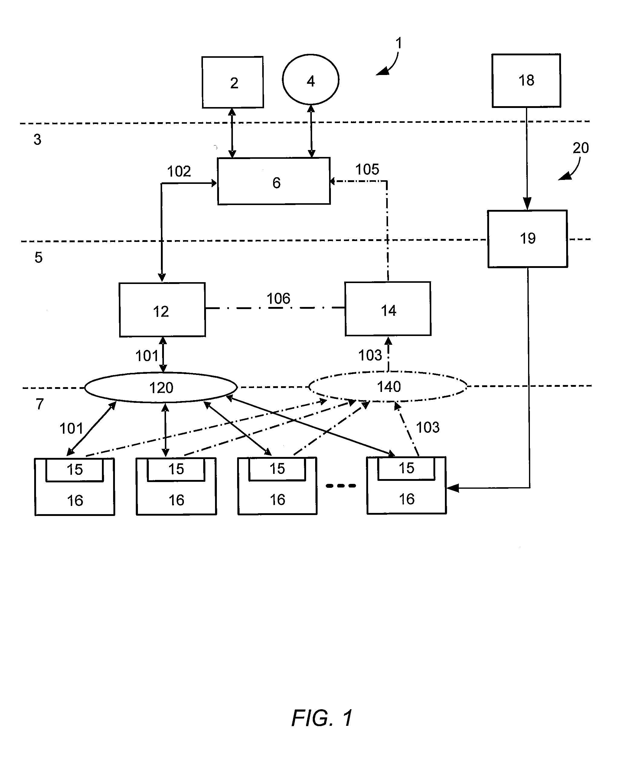
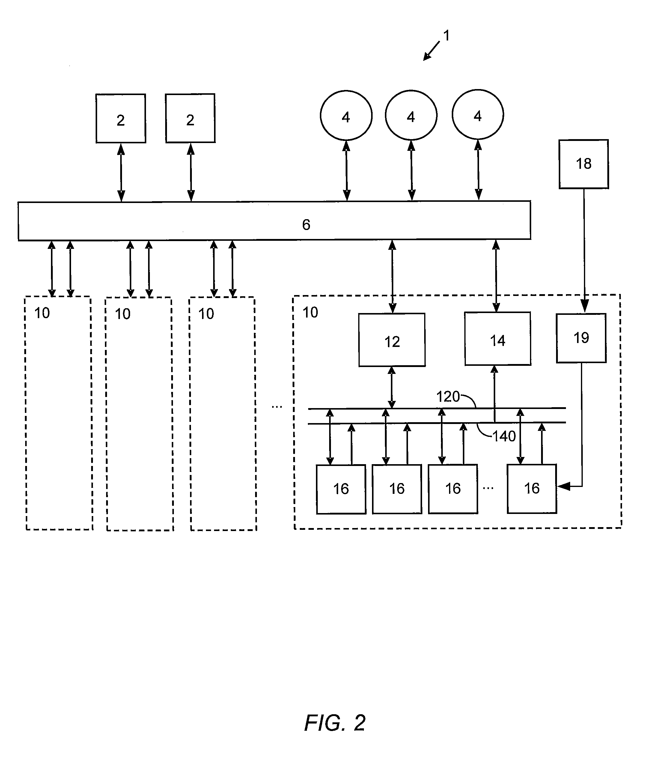
[0028]FIG. 1 is a schematic diagram of one embodiment of a lithography system 1 with control and data interfaces according to the invention. The diagram shows a hierarchical arrangement with three interfaces, a cluster interface 3, cluster element interface 5, and the lithography subsystem interfaces 7. FIG. 1 one illustrates a configuration with a lithography system cluster comprising one lithography element 10, which comprises multiple lithography subsystems 16. The lithography system may comprise multiple lithography elements 10, e.g. as in the FIG. 2 embodiment.

[0029]The cluster interface 3 comprises interfaces for communication between a lithography cluster front-end 6 and one or more host systems 2, and / or between the cluster front-end 6 and one or more operator consoles 4.

[0030]The cluster element interface 5 comprises interfaces for communication...


PUM


Abstract

The invention relates to a clustered substrate processing system comprising a plurality of lithography elements. Each lithography element is arranged for independent exposure of substrates according to pattern data, and comprises a plurality of lithography subsystems, a control network arranged for communication of control information between the lithography subsystems and at least one element control unit, the element control unit arranged to transmit commands to the lithography subsystems and the lithography subsystems arranged to transmit responses to the element control unit, and a data network arranged for communication of data logging information from the lithography subsystems to at least one data network hub, the lithography subsystems arranged to transmit data logging information to the data network hub and the data hub arranged for receiving and storing the data logging information. The system further comprises a cluster front-end for interface to an operator or host system.

Description

BACKGROUND OF THE INVENTION[0001]1. Field of the Invention[0002]The invention relates to a clustered substrate processing system comprising a plurality of lithography elements each arranged for independent exposure of substrates according to pattern data, and more particularly to network architecture for such a clustered substrate processing system.[0003]2. Description of the Related Art[0004]In the semiconductor industry, an ever increasing desire exists to manufacture structures with high accuracy and reliability. In lithography systems this desire results in extremely high demands with respect to the amount and the speed of production of wafers. Lithography machines have become more complex with numerous subsystems for performing various functions within the machine, and complex software to control the operation of the subsystems. Modern lithography machines typically generate large amounts of data operation and managing the data has become increasingly difficult. Lithography mac...

Claims


Application Information

Patent Timeline
Patent Type & Authority Applications(United States)
IPC IPC(8): G21K5/00
CPCG03F7/70508G03F7/70525G03F7/70991B82Y40/00G06F9/48B82Y10/00H01J37/3177G03F7/70483G05B19/41865G06F9/4881
Inventor SLOT, ERWINVAN KERVINCK, MARCEL NICOLAAS JACOBUSKUIPER, VINCENT SYLVESTER
Owner ASML NETHERLANDS BV
Why Eureka
Try Eureka