
Image processing apparatus and control method thereof

a technology of image processing and control method, applied in the field of image processing apparatus, can solve the problems of loss of fine unevenness, difficult to express the image of physical objects such as skin, marble, at a level comparable to the original image, etc., and achieve the effect of fine unevenness

Active Publication Date: 2013-02-14
CANON KK
View PDF7 Cites 1 Cited by
  • Summary
  • Abstract
  • Description
  • Claims
  • Application Information

AI Technical Summary

Benefits of technology

The invention allows for a better reproduction of the original image surface shape by blurring processing that takes into account the unevenness of the surface. This results in a more accurate representation of the surface shape.

Problems solved by technology

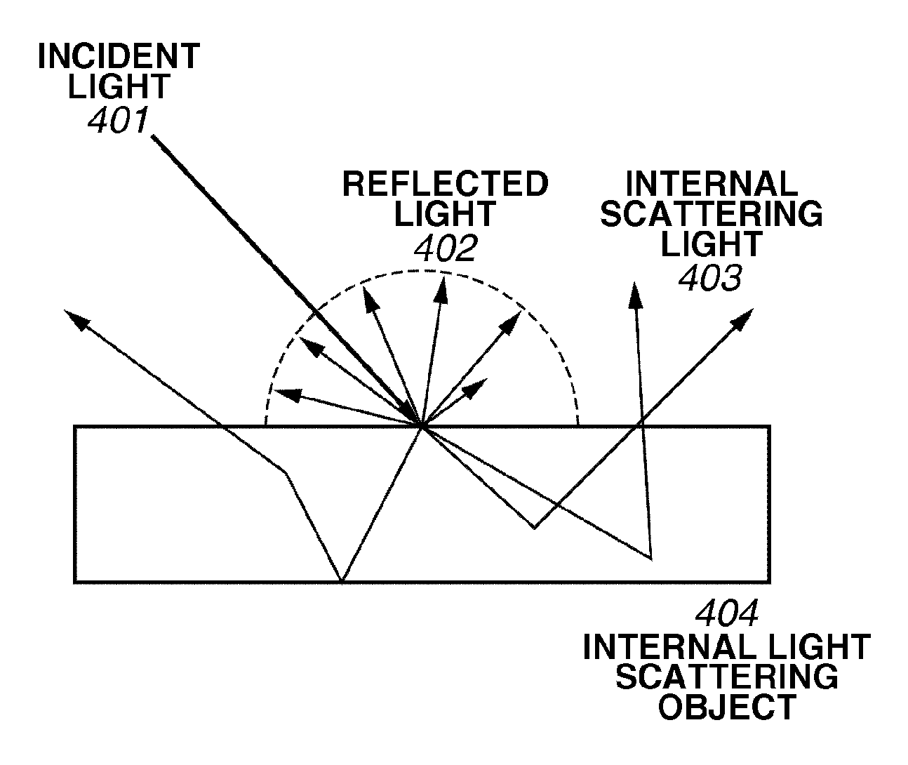
On the other hand, it is difficult for images of the physical objects such as skin, marble, milk, and the like, in which internal scattering of light is caused, to be expressed at a level equivalent to the original images.
In particular, the skin has fine unevenness on its surface, and therefore, it is difficult to express the image thereof in CG at a level comparable to the original image.
However, when the blurring processing is performed after reproducing the fine unevenness of the skin surface, there may be a case where the fine unevenness thereof is lost due to the blurring processing.

Method used


Image

  • Image processing apparatus and control method thereof
  • Image processing apparatus and control method thereof
  • Image processing apparatus and control method thereof

Examples


Embodiment Construction

[0028]Various exemplary embodiments, features, and aspects of the invention will be described in detail below with reference to the drawings.

[0029]A configuration described in the exemplary embodiments below is merely an example, and the invention is not limited thereto.

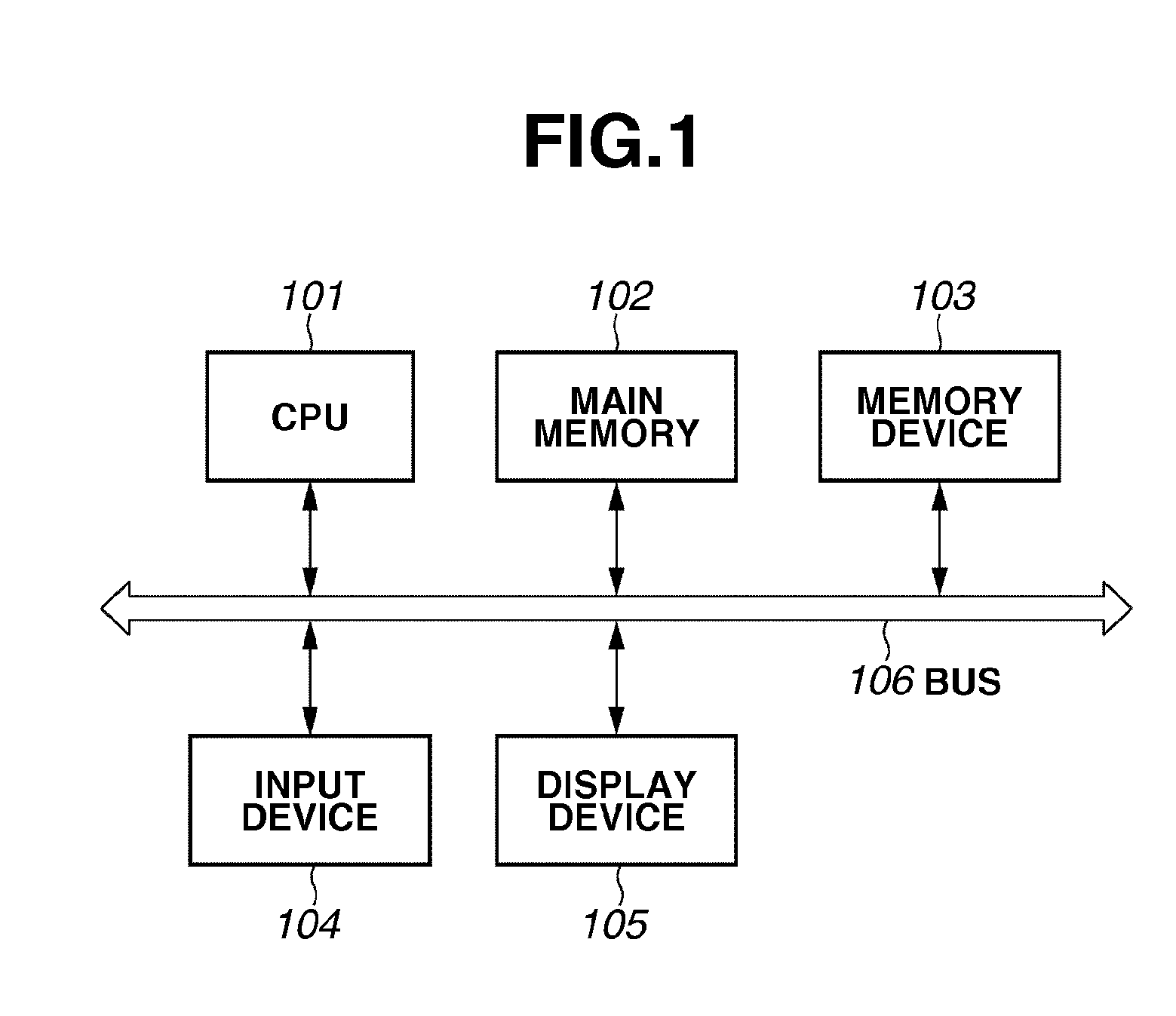
[0030]FIG. 1 is a block diagram illustrating a system configuration of a CG generation apparatus (i.e., image processing apparatus) that can be applied to the present exemplary embodiment. The CG generation apparatus includes a central processing unit (CPU) 101, a main memory 102, a memory device 103, an input device 104, a display device 105, and a bus 106. The CPU 101 executes an arithmetic processing and various programs. The main memory 102 provides the CPU 101 with a program, data, a work area, and so on, which are necessary for the processing.

[0031]The memory device 103 stores an image generation program, property data of a light source and an object. A hard disk drive may be used as the memory device 103, for ...


PUM


Abstract

An image processing apparatus configured to perform an appropriate blurring processing in which a height difference in the surface shape with fine unevenness is taken into consideration, and to reproduce the surface shape faithfully corresponding to an original image. The image processing apparatus for generating computer graphics expressing an object includes a first acquisition unit configured to acquire height information representing a relative height difference in a surface of the object, a second acquisition unit configured to acquire at least one scattering function representing an internal scattering characteristic of light in the object, and a calculation unit configured to calculate a luminance value of the object based on the height information and the scattering function.

Description

BACKGROUND OF THE INVENTION[0001]1. Field of the Invention[0002]The present invention relates to a technique capable of expressing, by using computer graphics (CG) technology, a physical object in which internal scattering of light is caused.[0003]2. Description of the Related Art[0004]Nowadays, using computer graphics (hereinafter, also called “CG”) enables images of physical objects such as metal, glass, and so on to be expressed at a level comparable to the original images. On the other hand, it is difficult for images of the physical objects such as skin, marble, milk, and the like, in which internal scattering of light is caused, to be expressed at a level equivalent to the original images.[0005]In particular, the skin has fine unevenness on its surface, and therefore, it is difficult to express the image thereof in CG at a level comparable to the original image. In order to express the skin image comparable to the original image, it is important to reproduce internal scatterin...

Claims


Application Information

Patent Timeline
Patent Type & Authority Applications(United States)
IPC IPC(8): G09G5/00
CPCG06T15/506
Inventor HANAMOTO, TAKASHI
Owner CANON KK
Learn More