Remote Control System

a remote control and image transmission technology, applied in the field of remote control systems, can solve the problems of limited field of view, inability to obtain images of objects in the forward upper direction or in the forward lower direction, and operator can only passively watch an image transmitted, so as to achieve the effect of higher remote operation efficiency

Active Publication Date: 2013-02-14
KK TOPCON
View PDF3 Cites 32 Cited by
  • Summary
  • Abstract
  • Description
  • Claims
  • Application Information

AI Technical Summary

Benefits of technology

[0007]It is an object of the present invention to provide a remote control system, by which an operator can obtain an image by a three-dimensional camera installed on a mobile object and can have a feeling as real as if it actually happens and with higher remote operation efficiency by modeling after the mobile object as seen from the operator.

Problems solved by technology

As a result, the operator can only passively watch an image transmitted from the three-dimensional camera, and field of view is also limited by the field angle of the three-dimensional camera.
Accordingly, it is not possible to obtain images of the object in forward upper direction or in forward lower direction or in forward leftward direction or forward rightward direction or in lateral direction.
Therefore, sufficient information on operation cannot be obtained at a narrow and confined place or at a place with many obstacles.

Method used


Image

  • Remote Control System
  • Remote Control System
  • Remote Control System

Examples


first embodiment

[0032]First, description is given below on a first embodiment where the present invention is applied as a remote control system of a small flying object.

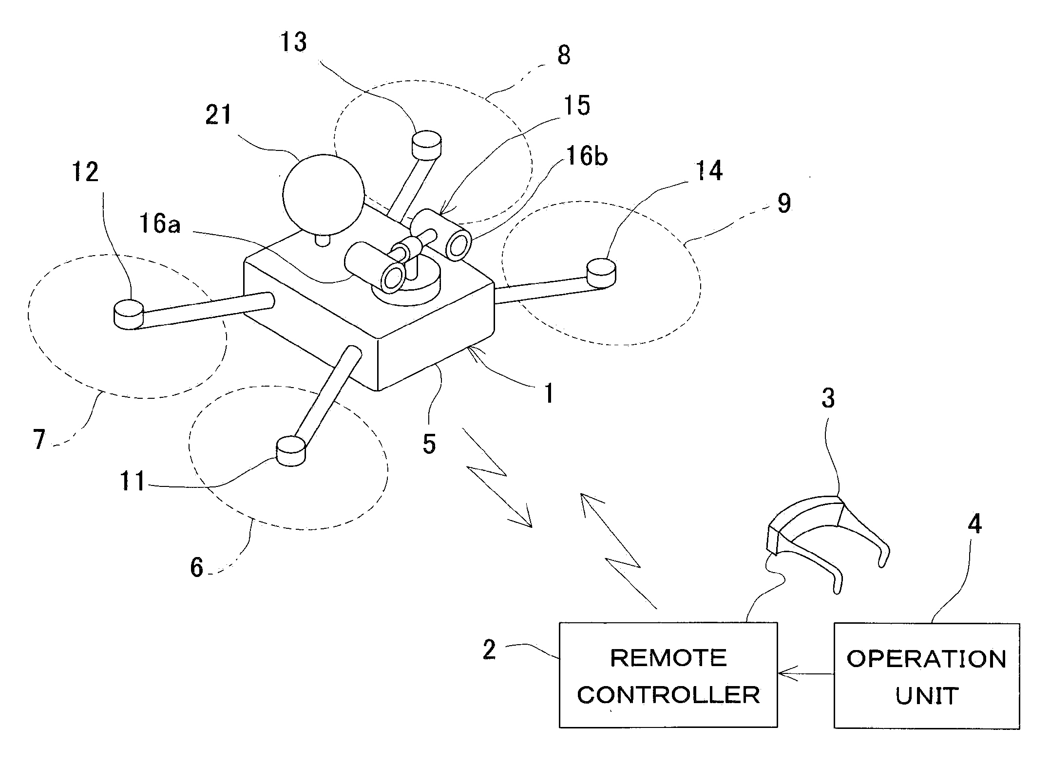
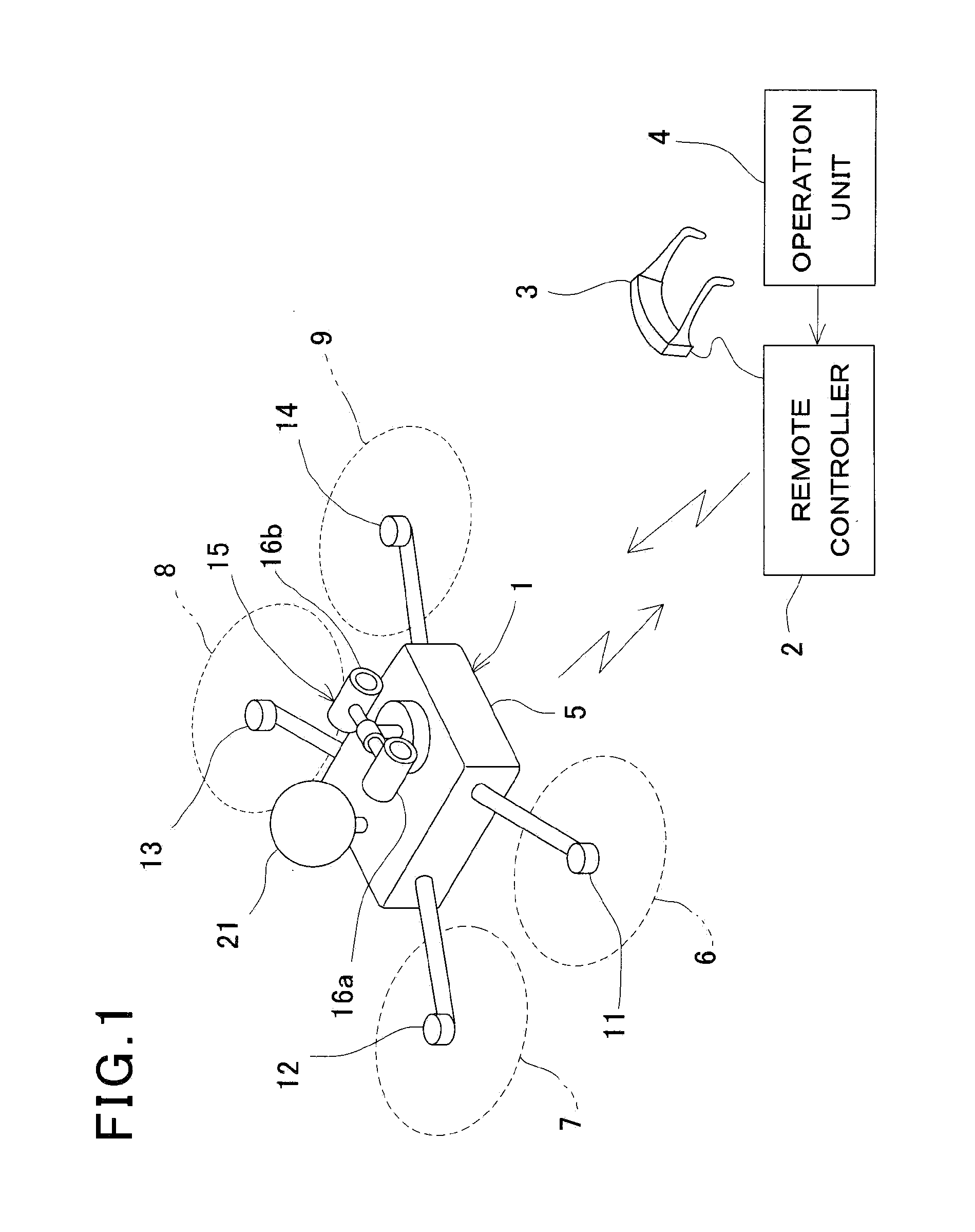
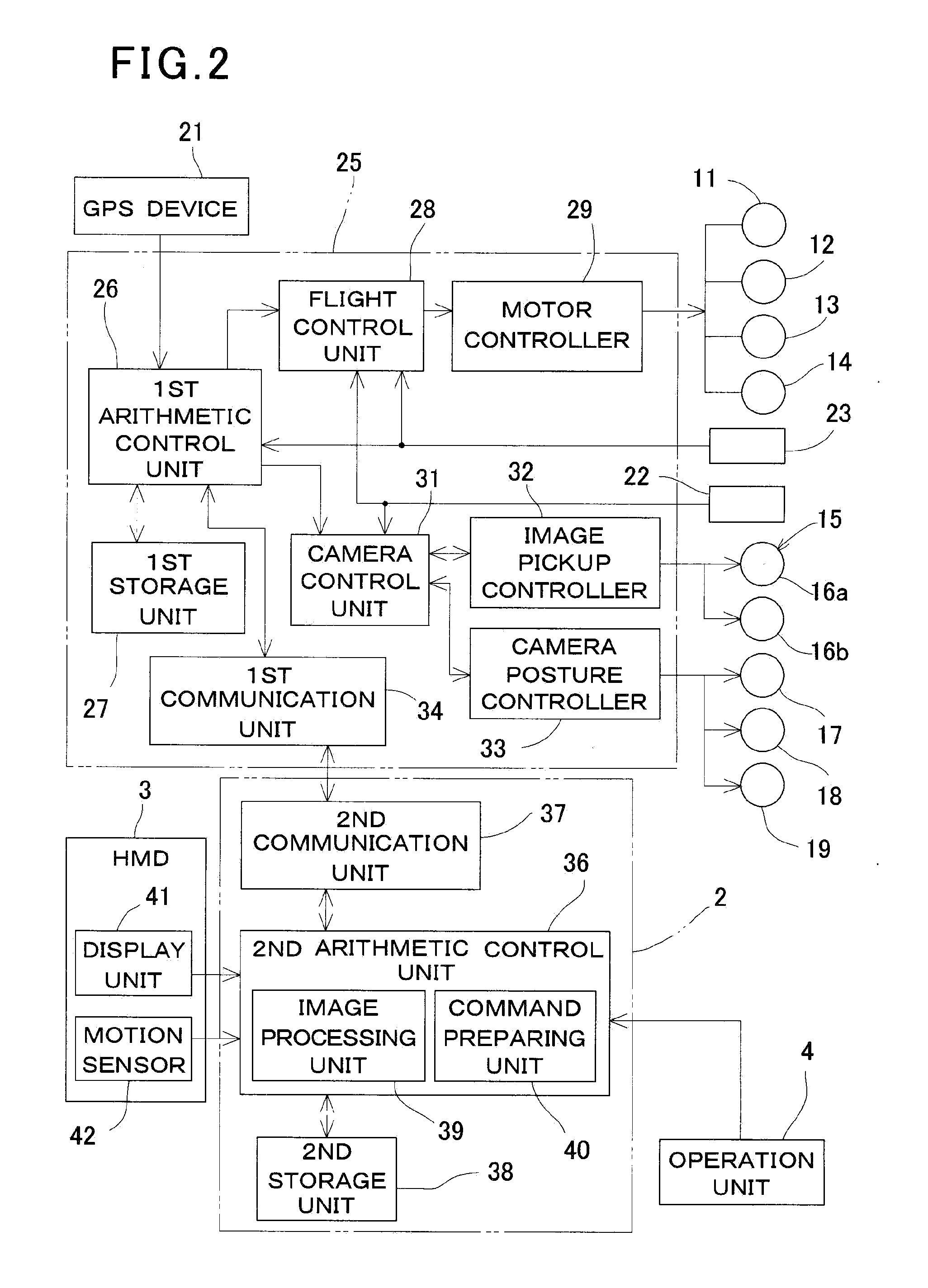
[0033]FIG. 1 and FIG. 2 each represents a basic arrangement of a remote control system according to a first embodiment. The remote control system primarily comprises a flying object 1, an operation unit 4, which has a remote controller 2, a head-mounted display (HMD) 3, a joy stick, etc. disposed on base station side. The flying object 1 is a helicopter as a small flying object, for instance, and the helicopter 1 can be remotely controlled by the remote controller 2.

[0034]The helicopter 1 comprises a helicopter body 5 and as many propellers as required mounted on the helicopter body 5 (e.g. propellers mounted at forward, rearward, leftward and right positions respectively, i.e. four propellers 6, 7, 8 and 9), and these propellers 6, 7, 8 and 9 are connected with a first flight motor 11, a second flight motor 12, a third flight motor...

second embodiment

[0073]Next, referring to FIG. 5, description will be given on a In FIG. 5, the same component shown in FIG. 4 is referred by the same symbol.

[0074]In the second embodiment, the object of the remote control operation is a small type running vehicle, e.g. a remotely controlled vehicle 61.

[0075]In the second embodiment, too, a stereo camera 15 is installed on a required position such as on a ceiling, for instance. The stereo camera 15 has two digital cameras 16a and 16b. The stereo camera 15 is rotatably supported on three axes, i.e. pitch axis, roll axis and yaw axis, and the stereo camera 15 can be controlled by rotating around each of these axes.

[0076]In case of the remotely controlled vehicle 61, moving means to drive the remotely controlled vehicle 61 are running motor wheels and a running motor to rotate the wheels. The means for controlling the running is the control of rotating speed (running speed) of the wheels and handle operation (in running direction). As a sensor to dete...


PUM


Abstract

A remote control system comprises a mobile object, a remote controller for remotely controlling the mobile object, and a storage unit where background images to simulate a driving room or an operation room of the mobile object are stored. The mobile object has a stereo camera, a camera control unit for controlling image pickup direction of the stereo camera, and a first communication unit for communicating information including at least images photographed by the stereo camera. The remote controller has a second communication unit for communicating to and from the first communication unit, a control unit for controlling the mobile object, and a display unit for synthesizing at least a part of the images photographed by the stereo camera and the background images and for displaying the images so that a stereoscopic view can be displayed.

Description

BACKGROUND OF THE INVENTION[0001]The present invention relates to a remote control system when a mobile object is remotely controlled by manual operation.[0002]In a case where a mobile object is remotely controlled, or in a case where a mobile object is remotely controlled in a range where the object cannot be visually confirmed, or in a case where precise operation is required even in a range where the mobile object can be visually confirmed, it is necessary to have information such as conditions of the mobile object or advancing direction of the mobile object.[0003]The Japanese Patent Application Publication JP-A-H8-280003 discloses the fact that a three-dimensional camera is mounted on the mobile object, and an image obtained by the three-dimensional camera is transmitted to an operator side, and the operator has a head-mounted display on his head and remotely controls the mobile object while watching an image, which is transmitted to the head-mounted display.[0004]According to t...

Claims


Application Information

Patent Timeline
Patent Type & Authority Applications(United States)
IPC IPC(8): H04N13/02
CPCG05D1/0038G05D1/0016
Inventor OHTOMO, FUMIOOSARAGI, KAZUKIANAI, TETSUJI
Owner KK TOPCON
Why Eureka
Try Eureka