Diffractive combiner for head-up color display device

a color display device and diffractive combiner technology, applied in the field of diffractive combiners, can solve the problems of complex implementation, high manufacturing cost, and allowing mass replication of combiners

Inactive Publication Date: 2013-02-14
DELPHI TECH INC +1
View PDF2 Cites 53 Cited by
  • Summary
  • Abstract
  • Description
  • Claims
  • Application Information

AI Technical Summary

Benefits of technology

[0009]The present invention remedies these inadequacies and proposes a solution that allows mass production of a diffractive combiner compatible with a “full-color” head-up display device.

Problems solved by technology

Their manufacturing costs are consequently often high, such as to prevent their commercial exploitation and their large-scale installation in low or medium range vehicles.
The said costs result in particular from the technologies used, which are complicated to implement and which moreover do not always allow mass replication of the combiners with a sufficient guarantee of stability of the optical characteristics.
Such a component can only be manufactured in individual units, as it involves a recording performed on an individual basis and it is not suitable for mass production at a reasonable industrial cost.
Moreover, this system only works in reflection.
Another structure with at least two layers is described in the patent U.S. Pat. No. 6,005,714, the multiplication of the layers increasing the difficulty of maintaining, during mass production, correct stability of the optical function to be provided.
The two alternatives firstly suffer from the great disadvantage that the optical diffraction gratings are formed on photosensitive plates (sensitive to UV radiation), which, in practice, makes the addition of protective layers necessary.
Now the fact of having to use a plurality of layers stuck or laminated together complicates the production of the combiner.
Another very big problem is the homogeneity of the different layers, mainly with regard to their ageing.
There is a risk of the layers becoming unstuck or of the optical properties of one or the other layer becoming degraded.
It follows that the implementation of a combiner such as described in document EP 0467328 is difficult and the result will always be a more or less successful compromise between several parameters to be optimized.
Such an adaptation would therefore cause still greater complexity.
Also, in the documents cited above the control of the diffraction efficiency is empirical and very limited, which implies a problem for the standardization of the luminance level of the virtual image obtained.

Method used


Image

  • Diffractive combiner for head-up color display device
  • Diffractive combiner for head-up color display device
  • Diffractive combiner for head-up color display device

Examples


Embodiment Construction

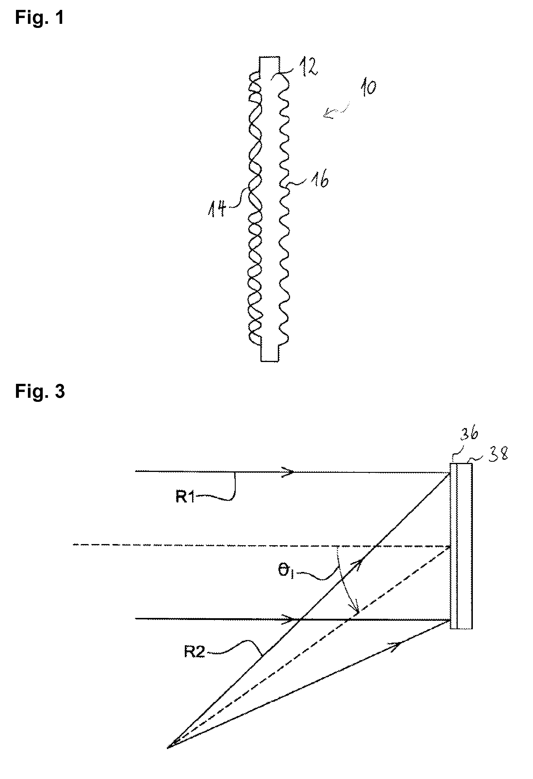
[0051]FIG. 1 shows diagrammatically a section of a diffractive combiner 10 for a “full-color” head-up display device. The combiner 10 comprises a support body 12 made of plastics material, e.g. PMMA, PC, PET, or PVB. The combiner 10 comprises a first 14 and a second 16 optical diffraction gratings formed in relief on the first and the second face respectively of the support body 12. Let us note that in FIG. 1 the dimensions of the combiner 10 are not to scale; in particular the thickness of the support body 12 and the amplitude (or the depth) of the reliefs are exaggerated. The thickness of the combiner is preferably within the range from 0.25 to 3 mm. The depth of the relief gratings is preferably within the range from 100 to 600 nm.

[0052]The first optical diffraction grating 14 is a multiplexed grating, while the second 16 is a single (non-multiplexed) grating.

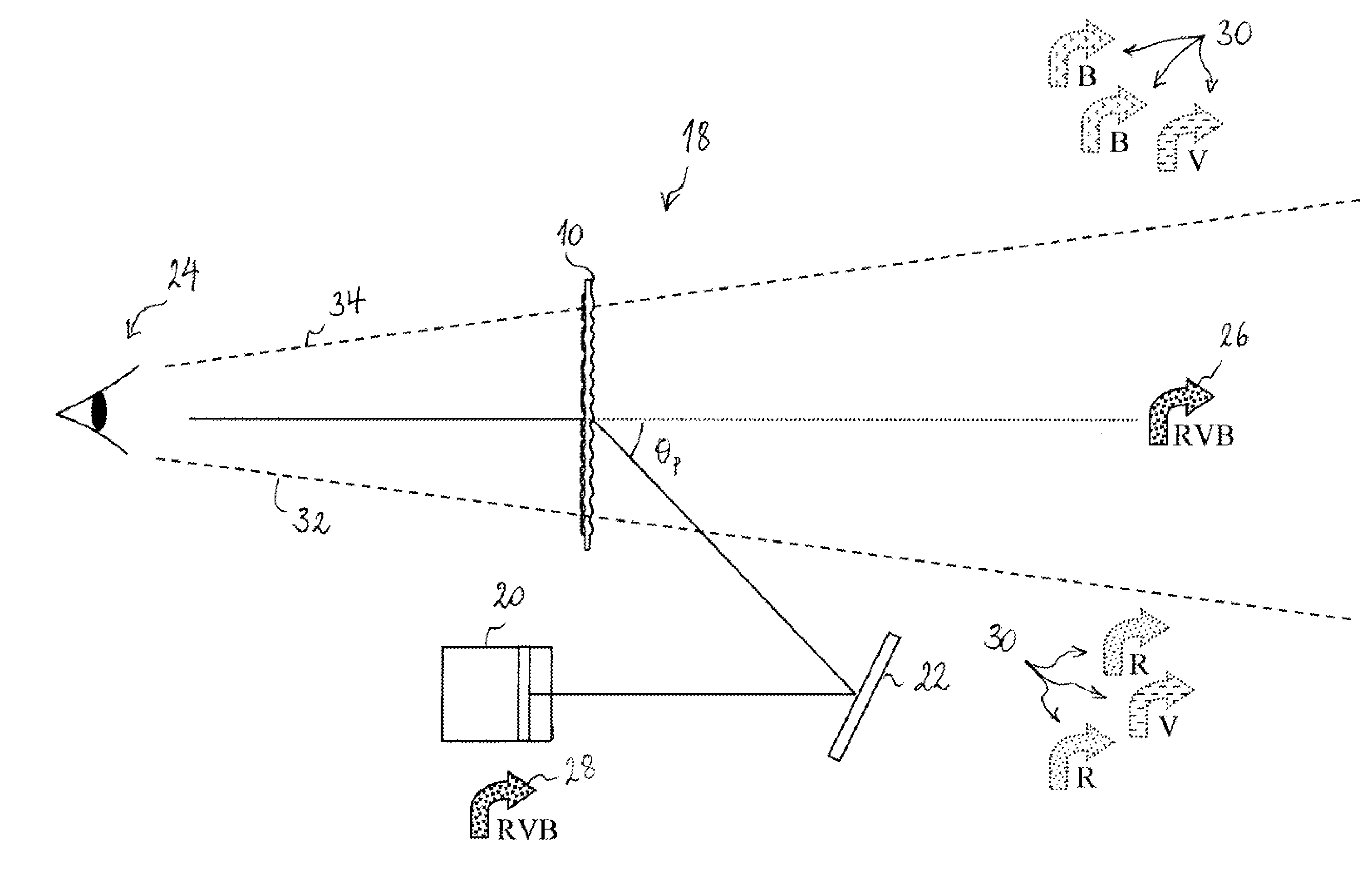
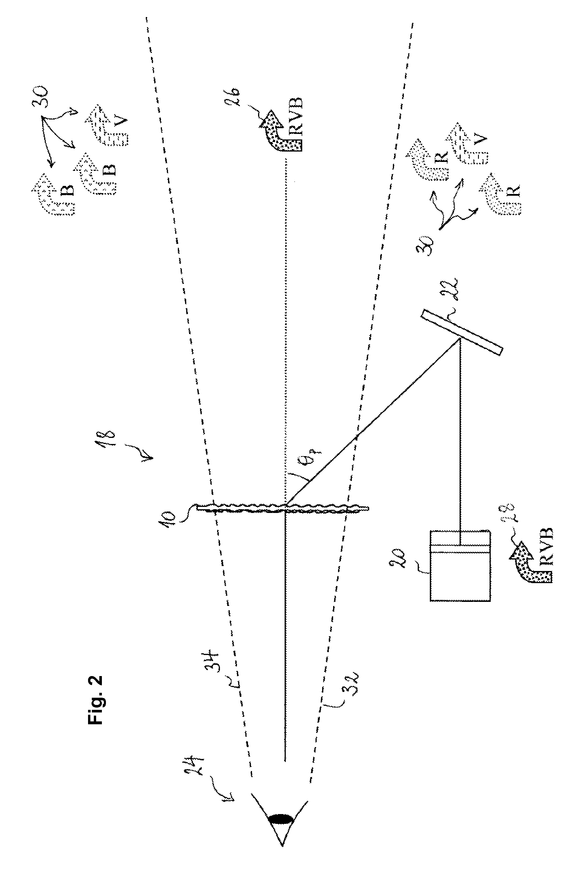
[0053]To explain the configuration of the optical diffraction gratings 14, 16 and the operation of the diffractive combine...


PUM


Abstract

A diffractive combiner for head-up color display device comprises a first optical diffraction grating configured to diffract, in a direction of diffraction, light of a first incident wavelength on the first grating in a direction of incidence, a second optical diffraction grating configured to diffract, in the same direction of diffraction, light of a second incident wavelength on the second grating in the direction of incidence. The first and second optical diffraction gratings are formed in relief on first and second opposed faces of the combiner. The first and / or the second grating is formed as a wavelength multiplexed optical diffraction grating and configured to diffract, in the direction of diffraction, light of a third incident wavelength on the first and / or second optical diffraction grating in the direction of incidence.

Description

CROSS-REFERENCE TO RELATED APPLICATION[0001]This application is a national stage application and claims the benefit under 35 U.S.C. §371 of published PCT Patent Application Number PCT / EP 2011 / 052477, filed Feb. 18, 2011, and was published as WO2011 / 113662 A1 on Sep. 22, 2011, the entire contents of which is hereby incorporated by reference herein.TECHNICAL FIELD OF INVENTION[0002]The present invention relates to a head-up display device particularly for a motor vehicle. In particular, the invention relates to a diffractive combiner for such a device, particularly for the display of information in color.BACKGROUND OF INVENTION[0003]A head-up display device typically includes a projection unit which produces a light beam intended to be directed towards a combiner for the projection of images, in particular operating or driving information of the vehicle in the form of a virtual image situated in the field of view of the driver. This type of device was initially made on the basis of te...

Claims


Application Information

Patent Timeline
Patent Type & Authority Applications(United States)
IPC IPC(8): G02B27/01G02B5/18
CPCG02B5/32G02B27/1086G02B27/0103G03H2001/266G03H1/0244G02B5/18
Inventor MOUSSA, HASSANEL HAFIDI, IDRISS
Owner DELPHI TECH INC
Why Eureka
Try Eureka