Dual electromagnetic valve and evaporated gas treatment system

a technology of electromagnetic valves and evaporated gas, applied in valve housings, combustion air/fuel air treatment, machines/engines, etc., can solve the problems of unfavorable pressure loss, reduced flow rate, and inability to make full use of the control capability (control flow rate) of each individual electromagnetic valve. achieve the effect of enhancing the treatment capability

Active Publication Date: 2013-02-21
MITSUBISHI ELECTRIC CORP
View PDF1 Cites 8 Cited by
  • Summary
  • Abstract
  • Description
  • Claims
  • Application Information

AI Technical Summary

Benefits of technology

[0013]According to the invention, through the use of the above dual electromagnetic valve, even an evaporated gas treatment system of a vehicle that is low in engin

Problems solved by technology

However, in Patent Document 1, the evaporated gas introduced from one inlet port to two electromagnetic valves is led out to respective outlet ports branching in two directions, and the outlet ports merge into one on the downstream side to be connected to the engine side; thus, there is a problem such that a pressure loss is unfavorably caused.
For this reason, the pressure loss causes the reduction of the flow rate, which makes it impossible to make full use of the control capability (control flow rate) of each individual electromagnetic valve.
Further, there are also the problem

Method used


Image

  • Dual electromagnetic valve and evaporated gas treatment system
  • Dual electromagnetic valve and evaporated gas treatment system
  • Dual electromagnetic valve and evaporated gas treatment system

Examples


embodiment 1

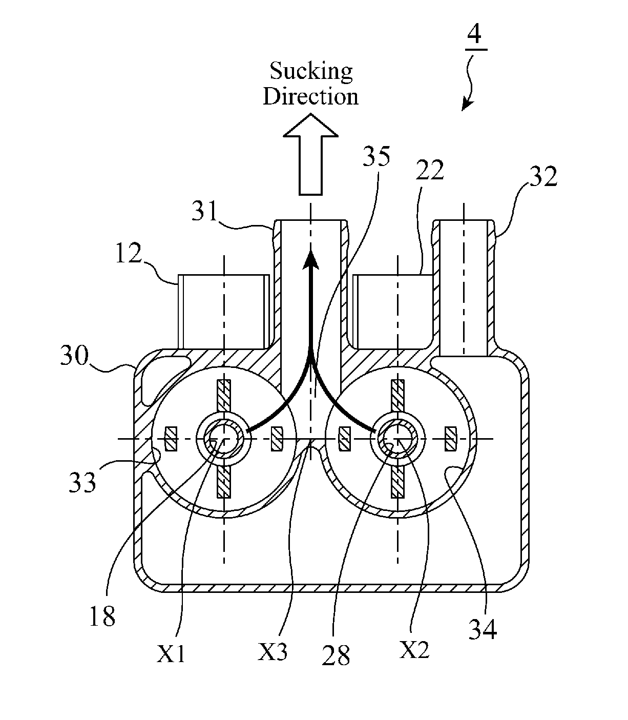
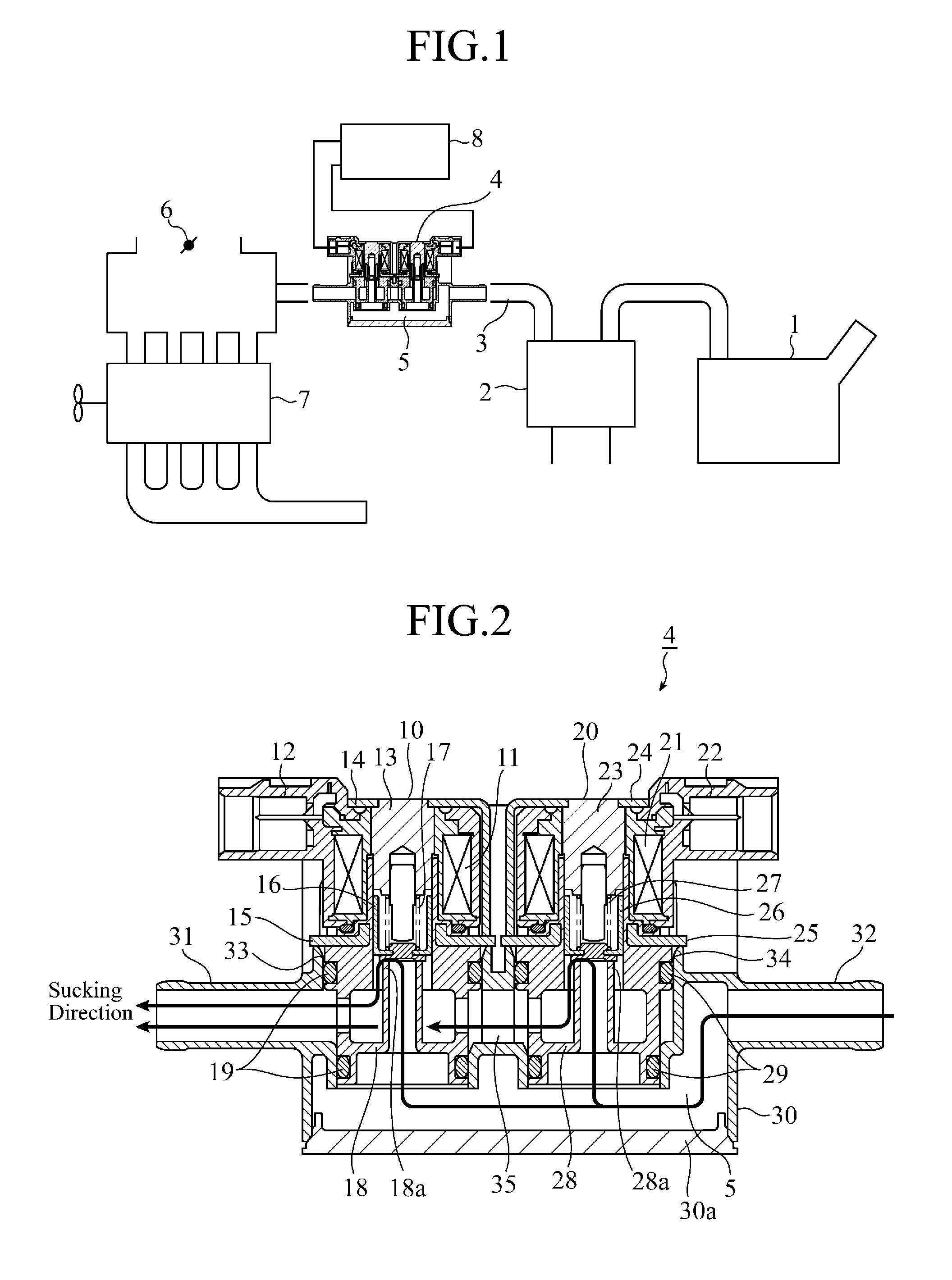
[0027]In an evaporated gas treatment system shown in FIG. 1, the evaporated gas volatilized in a fuel tank 1 is temporarily collected in a canister 2; through the use of the negative pressure produced in an engine 7, the evaporated gas is sucked from the canister 2 into the engine 7 for recombustion, thereby to be prevented from being discharged to the outside. In a suction path 3 connecting the canister 2 and the engine 7, a dual electromagnetic valve 4 integrated with a chamber 5 is arranged, and controls the amount of the evaporated gas in response to a driving signal from a control unit 8.

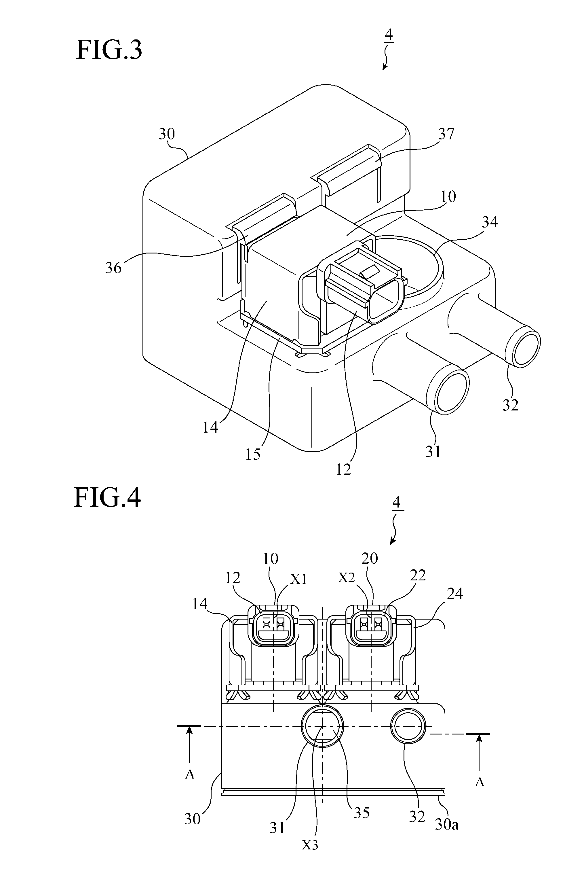
[0028]FIG. 2 is a longitudinal cross-sectional view showing the configuration of the dual electromagnetic valve 4. The dual electromagnetic valve 4 includes: a housing 30 composed of a suction port 31, a discharge port 32, and a chamber 5 communicating with the ports; a pair of electromagnetic valves 10 and 20 having tubular flow paths (flow path parts) 18 and 28 inserted into the chamber 5, an...

embodiment 2

[0064]In the above Embodiment 1, both the first electromagnetic valve 10 and the second electromagnetic valve 20 are provided in the reverse suction mode, but may also be provided in different suction modes.

[0065]FIG. 10 shows a configuration example of the dual electromagnetic valve 4 in which the suction modes of the first electromagnetic valve 10 and the second electromagnetic valve 20 are constituted differently. It is noted that the parts in FIG. 10 equal to or equivalent to those of FIGS. 2 to 6 are denoted by the same reference numerals and signs, and explanations thereof will be omitted.

[0066]In the present Embodiment 2, the first electromagnetic valve 10 is provided in the reverse suction mode in which the negative pressure application direction is equal to the valve opening direction of the plunger 16, and the negative pressure acts in the valve opening direction, while the second electromagnetic valve 20 is provided in the positive suction mode in which the negative press...


PUM


Abstract

A tubular flow path 18 of a first electromagnetic valve 10 and a tubular flow path 28 of a second electromagnetic valve 20 are inserted into a chamber 5 to communicate with a suction port 31 and a discharge port 32 to reduce a pulsating sound. The suction port 31 is arranged between the tubular flow paths 18 and 28 to reduce the air flow resistance.

Description

TECHNICAL FIELD[0001]The present invention relates to a dual electromagnetic valve for controlling the amount of an evaporated gas to be supplied from a fuel tank to an engine in an evaporated gas treatment system.BACKGROUND ART[0002]An evaporated gas treatment system of a vehicle enables the evaporated gas volatilized in a fuel tank to temporarily adsorb on a canister, and introduces the gas into the engine for recombustion using the engine negative pressure, thereby preventing the discharge of the gas to the outside. In recent years, the reduction of the engine operation frequency due to the trend of vehicles toward HEVs (Hybrid Electric Vehicles) or the like causes the reduction of the treatment capability of the evaporated gas treatment system using the engine negative pressure. In order to increase the flow rate of the evaporated gas to be supplied to the engine upon occurrence of the negative pressure corresponding to the reduction of the engine operation frequency, there has ...

Claims


Application Information

Patent Timeline
IPC IPC(8): F02M33/04F16K31/06G05D16/20
CPCF02M25/0836Y10T137/87314
Inventor TAKAHASHI, MASAJIITO, TAKAYUKI
Owner MITSUBISHI ELECTRIC CORP
Why Eureka
Try Eureka