

Cable holding structure
a technology of holding structure and cable, which is applied in the direction of electrical equipment, coupling device connection, and connection effected by permanent deformation, etc. it can solve the problems of electromagnetic noise generation, radio noise generation, and other problems, and achieve the effect of reducing electromagnetic nois
- Summary
- Abstract
- Description
- Claims
- Application Information
AI Technical Summary
Benefits of technology
Problems solved by technology
Method used
Image

Examples
first embodiment
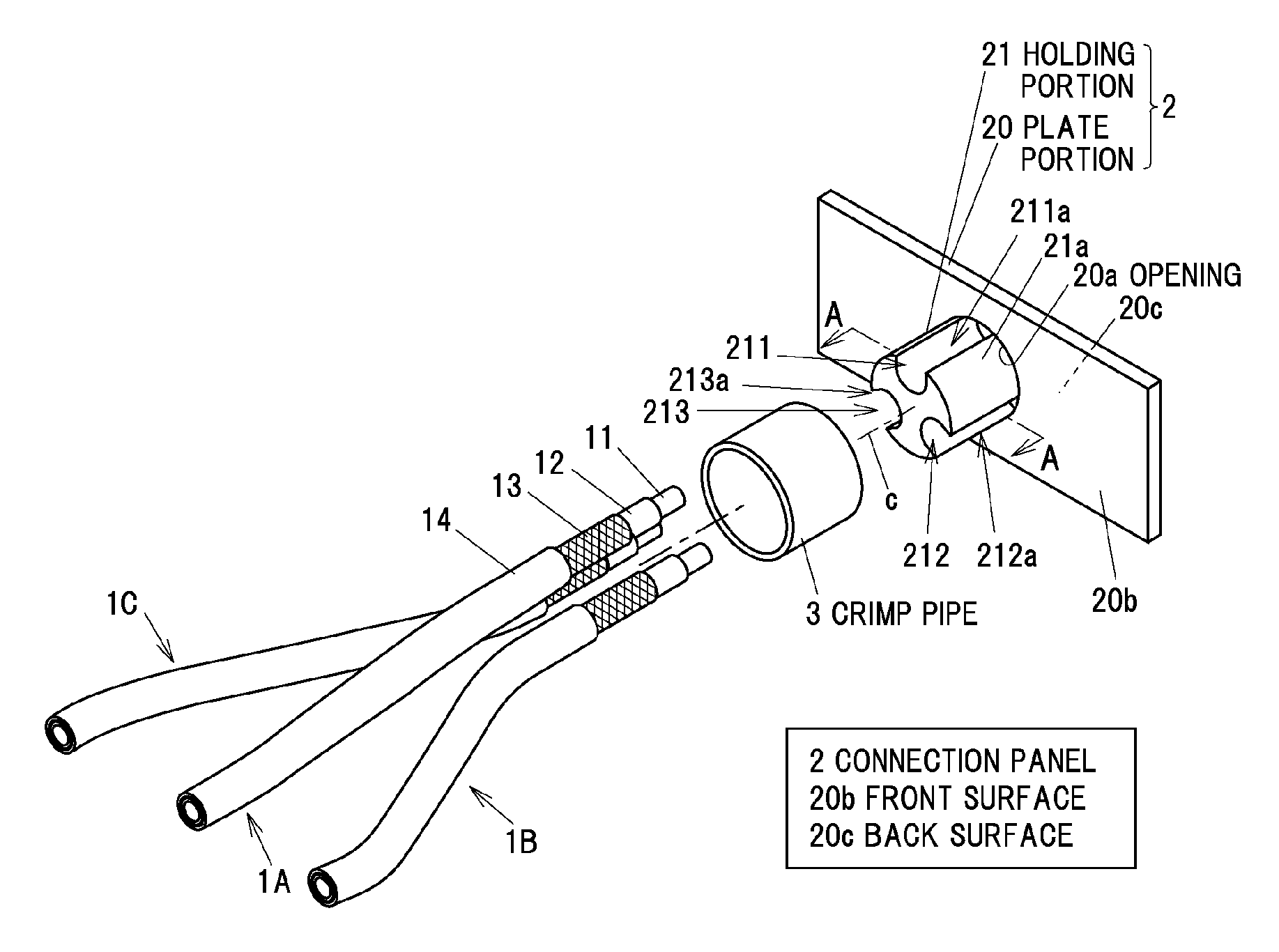
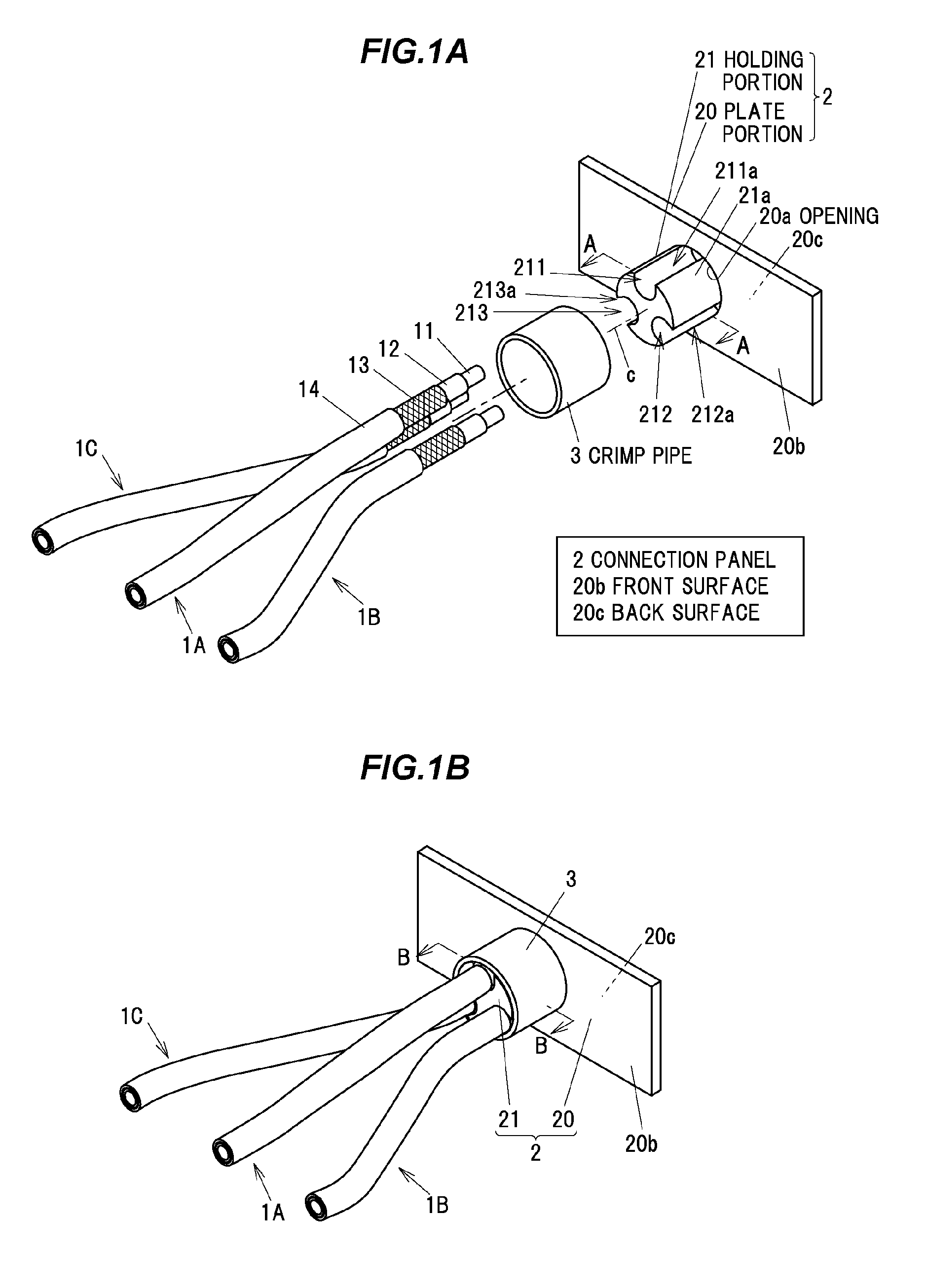
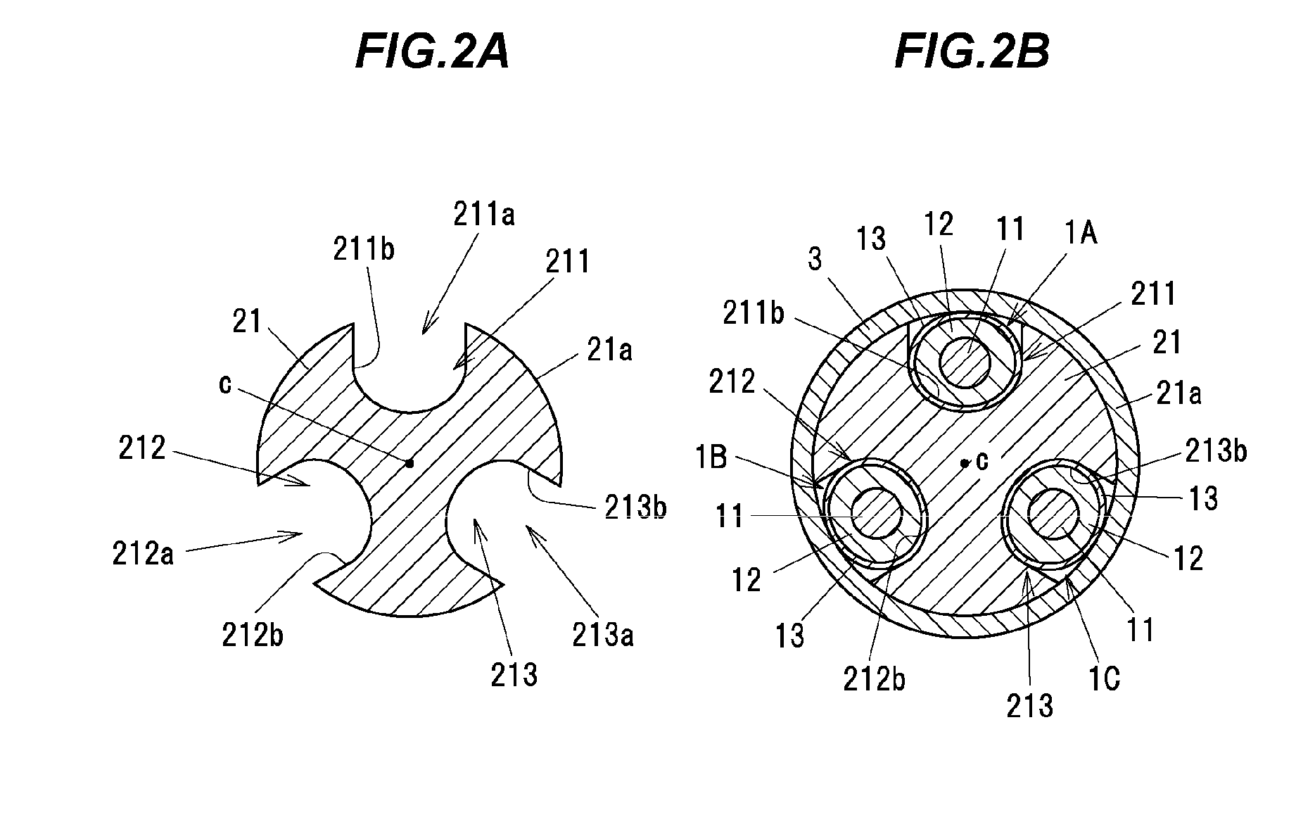
[0035]FIGS. 1A and 1B show a cable holding structure in the first embodiment of the invention, wherein FIG. 1A shows a state before holding three shielded cables 1A, 1B and 1C by a connection panel 2 and FIG. 1B shows a state in which the three shielded cables 1A, 1B and 1C are held by the connection panel 2. FIG. 2A is a cross sectional view taken on line A-A of FIG. 1A and FIG. 2B is a cross sectional view taken on line B-B of FIG. 1B.
[0036]The connection panel 2 is composed of a flat plate portion 20 and a columnar holding portion 21 provided thereon. A bolt (not shown) is inserted into an insertion hole (not shown) formed on the connection panel 2 and is screwed into a bolt hole formed on a case (not shown) of a device (e.g., an inverter device), thereby connecting and grounding the connection panel 2 to the case of the device (the same applies to the second, third and fourth embodiments). Note that, the connection panel 2 may be a portion of the case of the device (the same app...
second embodiment
[0054]FIGS. 4A and 4B show a cable holding structure in a second embodiment, wherein FIG. 4A is an exploded perspective view and FIG. 4B is a cross sectional view taken on line C-C of FIG. 4A. Members having the same functions as those described in the first embodiment are denoted by the same reference numerals in FIGS. 4A and 4B, and the overlapped explanation will be omitted.
[0055]In the first embodiment, the shield conductors 13 of the shielded cables 1A, 1B and 1C are directly in contact with the inner surfaces 211b, 212b and 213b of the through-holes 211, 212 and 213. On the other hand, in the second embodiment, the shield conductors 13 of the shielded cables 1A, 1B and 1C are respectively crimped by cylindrical small diameter crimp pipes 31 to 33 each formed to have a smaller diameter than the crimp pipe 3 and are then held in the through-holes 211, 212 and 213. The small diameter crimp pipes 31 to 33 are formed of a metal having conductivity such as copper, etc. The small dia...
third embodiment
[0060]Next, the third embodiment of the invention will be described in reference to FIGS. 5 to 6C. Members having the same functions as those described in the first embodiment are denoted by the same reference numerals in FIGS. 5 to 6C, and the overlapped explanation will be omitted.
[0061]FIG. 5 is a perspective view showing a connection panel 4 in the third embodiment.
[0062]In the connection panel 4 in the third embodiment, a holding portion 41 is press-fitted into and fixed to a rounded-rectangle-shaped opening 40a formed on a flat plate portion 40.
[0063]Three through-holes 411, 412 and 413 extending in a direction crossing the plate portion 40 are formed on the holding portion 41 so as to be aligned in one direction. In the third embodiment, the through-holes 411, 412 and 413 are formed along a direction orthogonal to the plate portion 40 so as to be parallel to each other.
[0064]In addition, an outer peripheral opening 411a for opening the through-hole 411 to the outside in a rad...
PUM
 Abstract
Description
Claims
Application Information