
Real Time Reconstruction of 3D Cylindrical Near Field Radar Images Using a Single Instruction Multiple Data Interpolation Approach

a near field radar and multi-data technology, applied in the inter-field field, can solve the problems of non-linear signature formation, execution time, and difficulty in correctly determining the dimensions and locations of the different scattering structures present in the scan area, and achieve the effects of significant reducing the reconstruction time, high performance computing capability, and low cos

Inactive Publication Date: 2013-02-21
TAPIA DANIEL FLORES +1
View PDF5 Cites 6 Cited by
  • Summary
  • Abstract
  • Description
  • Claims
  • Application Information

AI Technical Summary

Benefits of technology

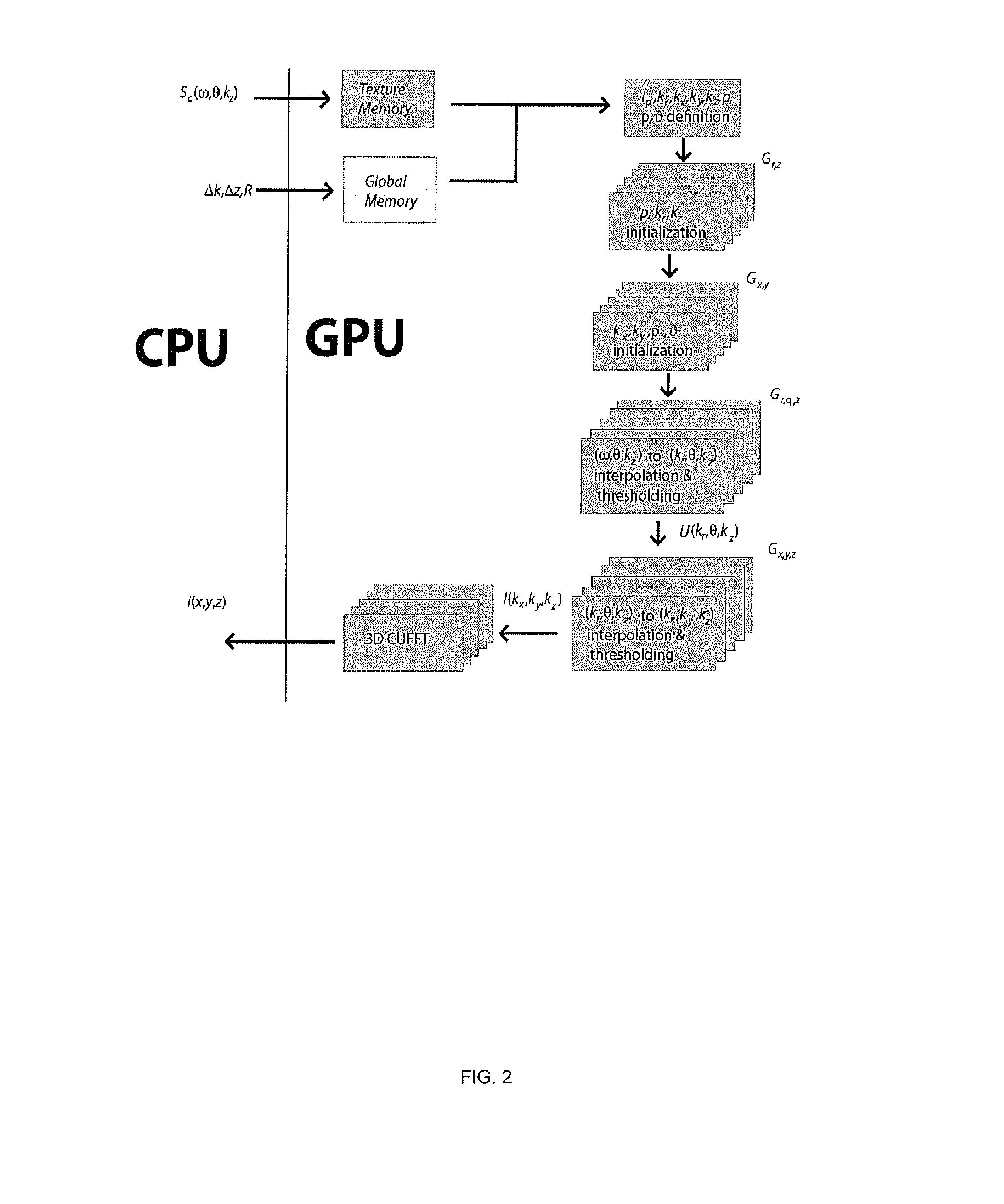
The proposed approach uses a new way to interpolation that reduces the time it takes to reconstruct images while keeping them accurate and detailed. This is done by processing each point in the problem space independently, making use of the high performance computing capabilities of a General Purpose Graphics Processing Unit (GPGPU). The technique was developed using a set of simulated and experimental data sets to measure its performance. The results show that the proposed method has faster execution times and higher signal to noise ratios than other methods, while maintaining spatial accuracy. This makes it a useful tool for reconstruction in a range of fields such as medical imaging or computer graphics.

Problems solved by technology

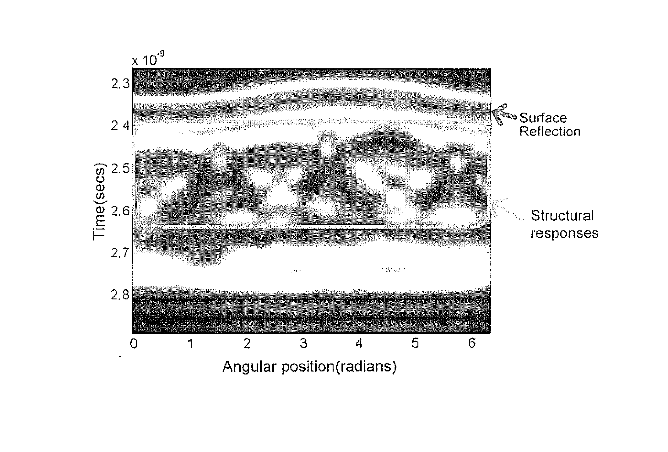
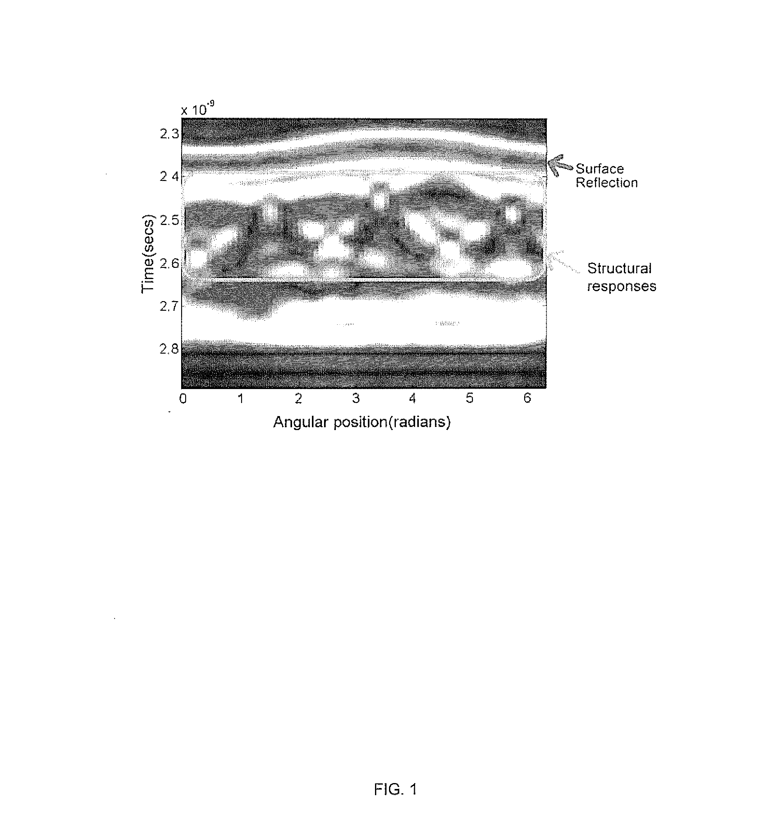
As the irradiation is performed along the scan trajectory, the target responses have different travel times, resulting in the formation of non-linear signatures.
This makes it difficult to correctly determine the dimensions and locations of the different scattering structures present in the scan area.
A problem with cylindrical radar reconstruction approaches is their execution time.
This can be an issue in cylindrical near field radar applications, due to the fact that a low execution time is required to provide the high throughput that is needed.

Method used


Image

  • Real Time Reconstruction of 3D Cylindrical Near Field Radar Images Using a Single Instruction Multiple Data Interpolation Approach
  • Real Time Reconstruction of 3D Cylindrical Near Field Radar Images Using a Single Instruction Multiple Data Interpolation Approach
  • Real Time Reconstruction of 3D Cylindrical Near Field Radar Images Using a Single Instruction Multiple Data Interpolation Approach

Examples


Embodiment Construction

Cylindrical SR Imaging.

Signal Model

[0098]Let us consider a cylindrical scan geometry with M scan planes defined along the z axis and N scan locations arranged in a circular pattern with a radius R at each plane. The irradiating antenna is facing towards the center of the scan plane. T point scatters are assumed to be inside the area delimited by the scan geometry. A waveform f(t) with a bandwidth B, is sequentially radiated from each scan location and the responses from the targets with the scan area are recorded at the same position. This signal is considered to have a length of L samples. For the scan location at (R, θ, z), the received signal can be expressed as:

s(t,θ,z)=∑q=1Tσqf(t-2Dq(θ,z)v)(1)

[0099]where v is the medium propagation speed, σq and (rp, φq, zp) are the reflectivity and polar coordinates of the qth target, and Dq(θ,z)=√{square root over (R2+rq2+(zq−z)2−2Rrq cos(φq−θ))}{square root over (R2+rq2+(zq−z)2−2Rrq cos(φq−θ))}.

[0100]In cylindrical SR scenarios, target refle...


PUM


Abstract

The present invention uses a Single Instruction Multiple Data (SIMD) architecture to form real time 3D radar images recorded in cylindrical near field scenarios using a wavefront reconstruction approach. A novel interpolation approach is executed in parallel, significantly reducing the reconstruction time without compromising the spatial accuracy and signal to noise ratios of the resulting images. Since each point in the problem space can be processed independently, the proposed technique was implemented using an approach on a General Purpose Graphics Processing Unit (GPGPU) to take advantage of the high performance computing capabilities of this platform.

Description

[0001]This application claims the benefit under 35 U.S.C. 119(e) of U.S. provisional application Ser. No. 61 / 525,290, filed Aug. 19, 2011.FIELD OF THE INVENTION[0002]The present invention relates to the use of a Single Instruction Multiple Data (SIMD) architecture to form real time 3D radar images recorded in cylindrical near field scenarios using a wavefront reconstruction approach, and more particularly, the present invention relates to an interpolation approach that is executed in parallel.BACKGROUND[0003]During the last three decades, subsurface radar (SR) imaging has proven to be a reliable tool for imaging and sensing a number of scenarios. This imaging technology is based on the dielectric differences between the materials that form the scan region propagation medium and the targets present inside it. In recent years, cylindrical scan trajectories have been used in some novel near field radar applications, such as Microwave Wood Inspection (MWI) and Breast Microwave Radar (BM...

Claims


Application Information

Patent Timeline
Patent Type & Authority Applications(United States)
IPC IPC(8): G01S13/89
CPCG01S13/426G01S13/89
Inventor TAPIA, DANIEL FLORESPISTORIUS, STEPHEN
Owner TAPIA DANIEL FLORES
Learn More