Cyclic Pitch Control System for Wind Turbine Blades

Inactive Publication Date: 2013-02-21
CLIPPER WINDPOWER INC
View PDF6 Cites 60 Cited by
  • Summary
  • Abstract
  • Description
  • Claims
  • Application Information

AI Technical Summary

Benefits of technology

[0007]In one aspect of the disclosure, a method to enhance the tower shadow effect, i.e. the normal tendency for each blade to produce less power and to actually unload or bend away from the tower is provided. The tower shadow effect results from lower wind speeds that normally exist immediately in front of the tower. As a result, a pitch control algorithm adapted to pitch an individual blade toward its feathered position as its tip advances toward the tower will cause that blade to unload and/or to spring away from the tower by an even greater distance to thus create a greater blade tip to tower clearance.
[0008]Another aspect of this disclosure is a further enhancement of overall wind turbine performance by superimposing an open loop pitch control algorithm on each individual blade, based primarily on th

Problems solved by technology

None of these proposed strategies have suggested an individual blade pitch control strategy for incr

Method used


Image

  • Cyclic Pitch Control System for Wind Turbine Blades
  • Cyclic Pitch Control System for Wind Turbine Blades
  • Cyclic Pitch Control System for Wind Turbine Blades

Examples


Embodiment Construction

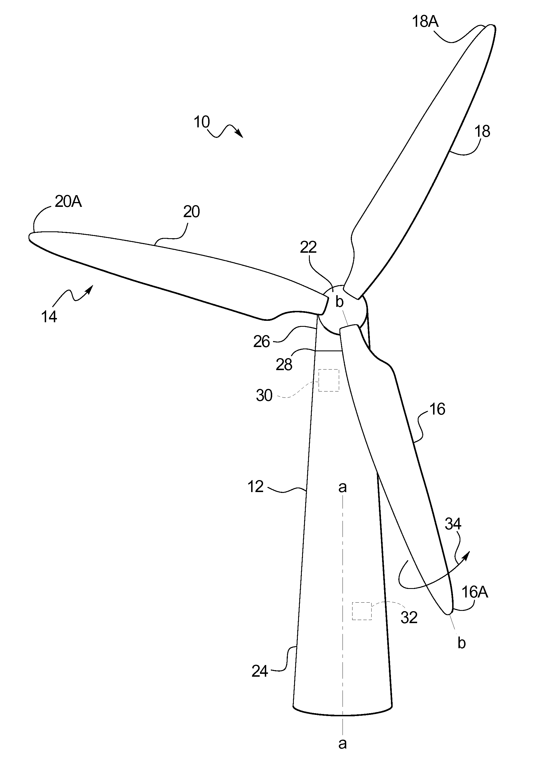
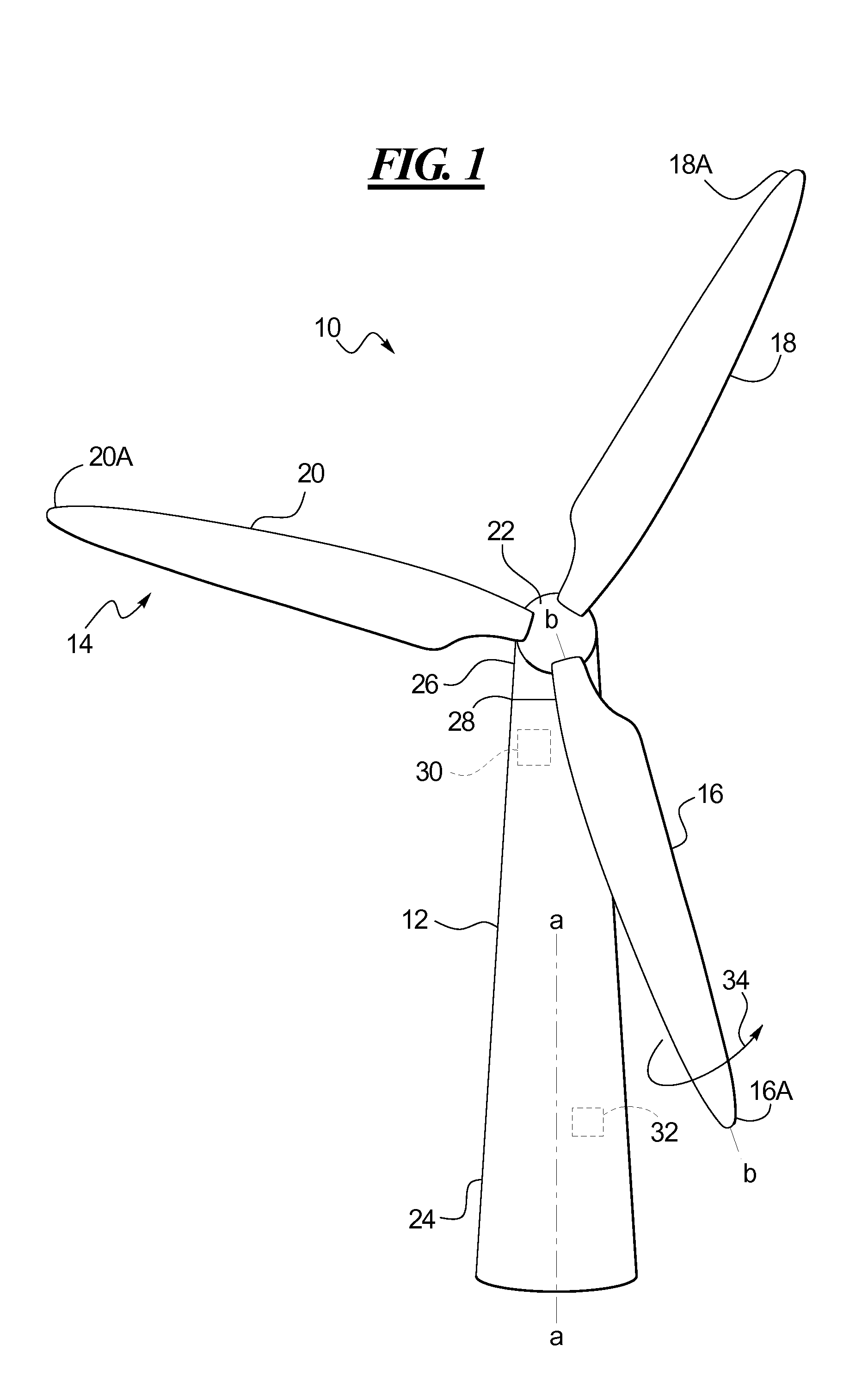
[0015]Referring initially to FIG. 1, an exemplary wind turbine 10 is schematically shown in accordance with at least one embodiment of the present disclosure. While all components of the wind turbine are not shown or described herein, the wind turbine 10 may include a vertically standing tower 12 having an axis “a-a”, and supporting a rotor 14. The rotor is defined by a collective plurality of equally spaced rotating blades 16, 18, and 20, each connected to and radially extending from a hub 22, as shown. The blades 16, 18, 20 may be rotated by wind energy such that the rotor 14 may transfer such energy via a main shaft (not shown) to one or more generators (not shown). Those skilled in the art will appreciate that such wind-power driven generators may produce commercial electric power for transmission to an electric grid (not shown). Those skilled in the art will appreciate that a plurality of such wind turbines may be effectively employed on a so-called wind turbine farm to generat...


PUM


Abstract

In a wind turbine, an open loop control algorithm for incrementally or positively adjusting the pitch angles of individual rotor blades may be used to increase spacing between the base of the turbine tower and an approaching blade tip. As each rotating blade passes in front of the tower base, a minimum clearance distance may be assured to avoid blade tip strikes of the base. In accordance with at least one embodiment of the control algorithm, as each blade approaches the tower base, it may be feathered to reduce its power loading, and to facilitate increased clearance beyond the normal unloading or feathering produced by the so-called tower shadow effect. To offset resultant loss of torque, the remaining blades may be correspondingly pitched toward power, i.e. into the wind, to balance and/or smooth out the overall rotor torque curve, and thus to avoid torque ripples.

Description

TECHNICAL FIELD[0001]This disclosure relates to control systems for managing operations of wind turbines. More particularly, the disclosure provides control algorithms for selectively varying the pitch angle of individual turbine rotor blades to increase the distance between a blade tip and the tower as the blade tip crosses in front of the tower.BACKGROUND[0002]Changing the pitch of the rotor blades of a utility scale wind turbine is commonly used as a primary control mechanism. The blades are pitched toward a power pitch position (i.e., at a lower pitch angle or into greater influence of the wind) to increase the amount of wind energy captured by the rotor, in turn increasing torque on the main shaft of the wind turbine to drive electric generators. The blades are pitched toward a feather position (at a higher pitch angle or away from influence of the wind) to decrease wind energy captured by the rotor, and to decrease torque on the main shaft.[0003]The reaction torque created by ...

Claims


Application Information

Patent Timeline
IPC IPC(8): F03D7/04
CPCF03D7/0224F03D7/024Y02E10/723F05B2270/17F03D7/043Y02E10/72
Inventor TAYLOR, NATHANIEL BROOK
Owner CLIPPER WINDPOWER INC
Why Eureka
Try Eureka