Magneto-rheological clutch with sensors measuring electromagnetic field strength

a magnetic field strength and electromagnetic field technology, applied in the field of torque transmission systems, can solve the problems of unable to meet the requirements of the current solution, unable to guarantee the safety of the operation, and many injuries each, and general reluctance to adopt such a technology as a viable alternative to the current solution

Inactive Publication Date: 2013-02-28
UNIV OF WESTERN ONTARIO
View PDF11 Cites 37 Cited by
  • Summary
  • Abstract
  • Description
  • Claims
  • Application Information

AI Technical Summary

Benefits of technology

[0018]The present invention provides systems and method relating to a clutch system for use in controllably transmitting torque from an input shaft to an output shaft. A clutch system is equipped with input and output torque transmission disks coupled respectively to input and output shafts. The input and output torque transmission disks are interleaved with one another and a torque transmission fluid is placed in between the interleaved tran

Problems solved by technology

Guaranteeing safety is a difficult if not impossible exercise as we can rarely guarantee the dependability of the numerous components required to complete a modern manipulator.
Such collisions are responsible for numerous injuries each year, despite the existence of barriers, and other fail-safe mechanisms.
While it has been suggested in the literature how such devices might be used in a manipulator to improve both safety and performance, there appears to be a general reluctance towards adopting such technology as a viable alternative to the current solutions.
There are several sources of danger when working closely with robotic devices.
However, collisions involving robots and humans pose arguably the largest

Method used


Image

  • Magneto-rheological clutch with sensors measuring electromagnetic field strength
  • Magneto-rheological clutch with sensors measuring electromagnetic field strength
  • Magneto-rheological clutch with sensors measuring electromagnetic field strength

Examples


Embodiment Construction

[0076]Magneto-rheological (MR) and electro-rheological (ER) fluids are a suspension of micrometer-sized particles in a carrier fluid. When subjected to an externally applied field—a magnetic field for MR fluids, and an electric field for ER fluids, the particles aggregate into columns aligning themselves in the direction of the applied field. Subsequently, the columns act to resist shearing of the fluid perpendicular to the field. The apparent yield stress of the fluid is dependent on, and increases with the intensity or strength of the applied field.

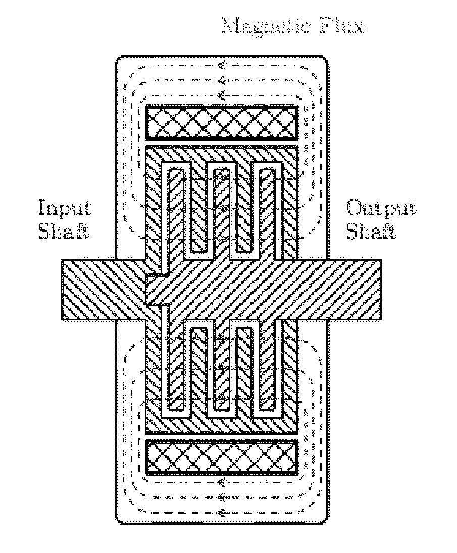
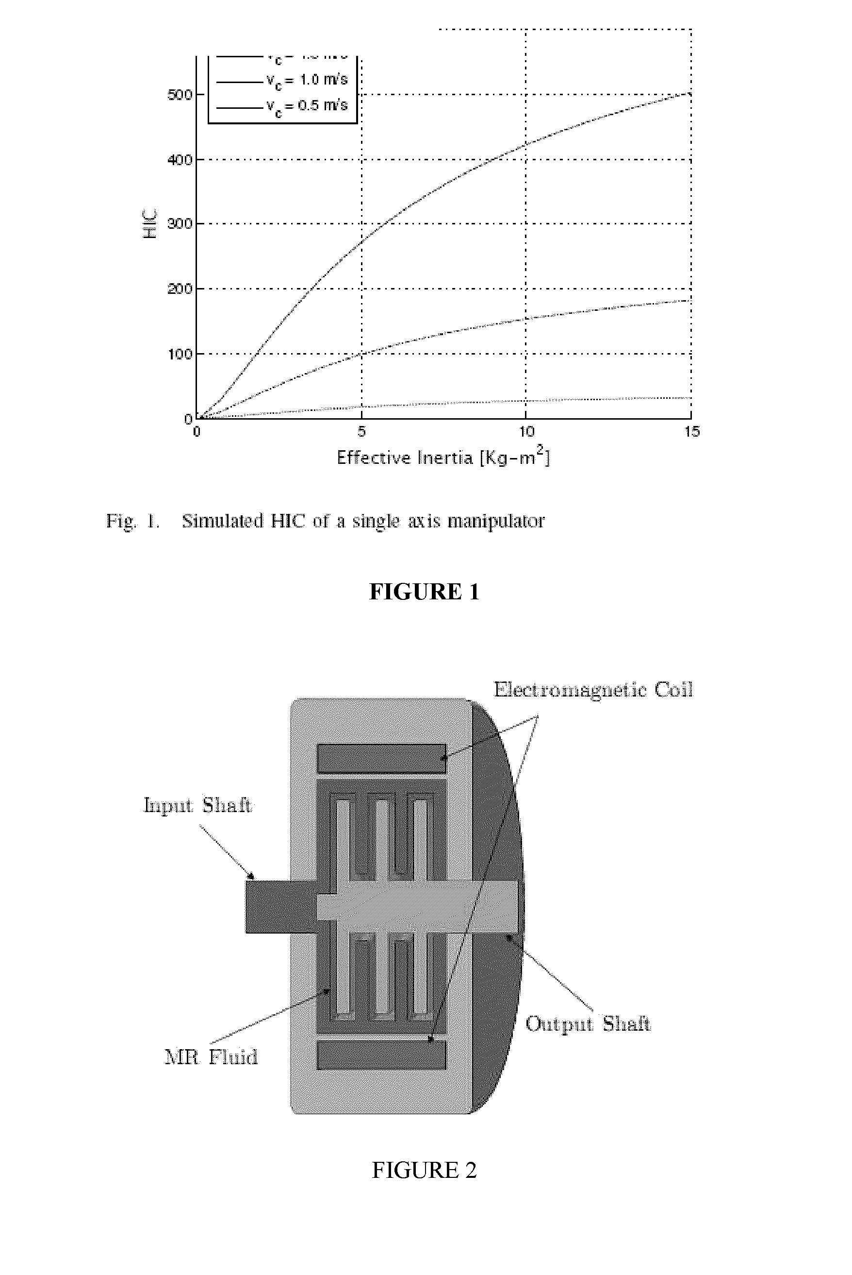
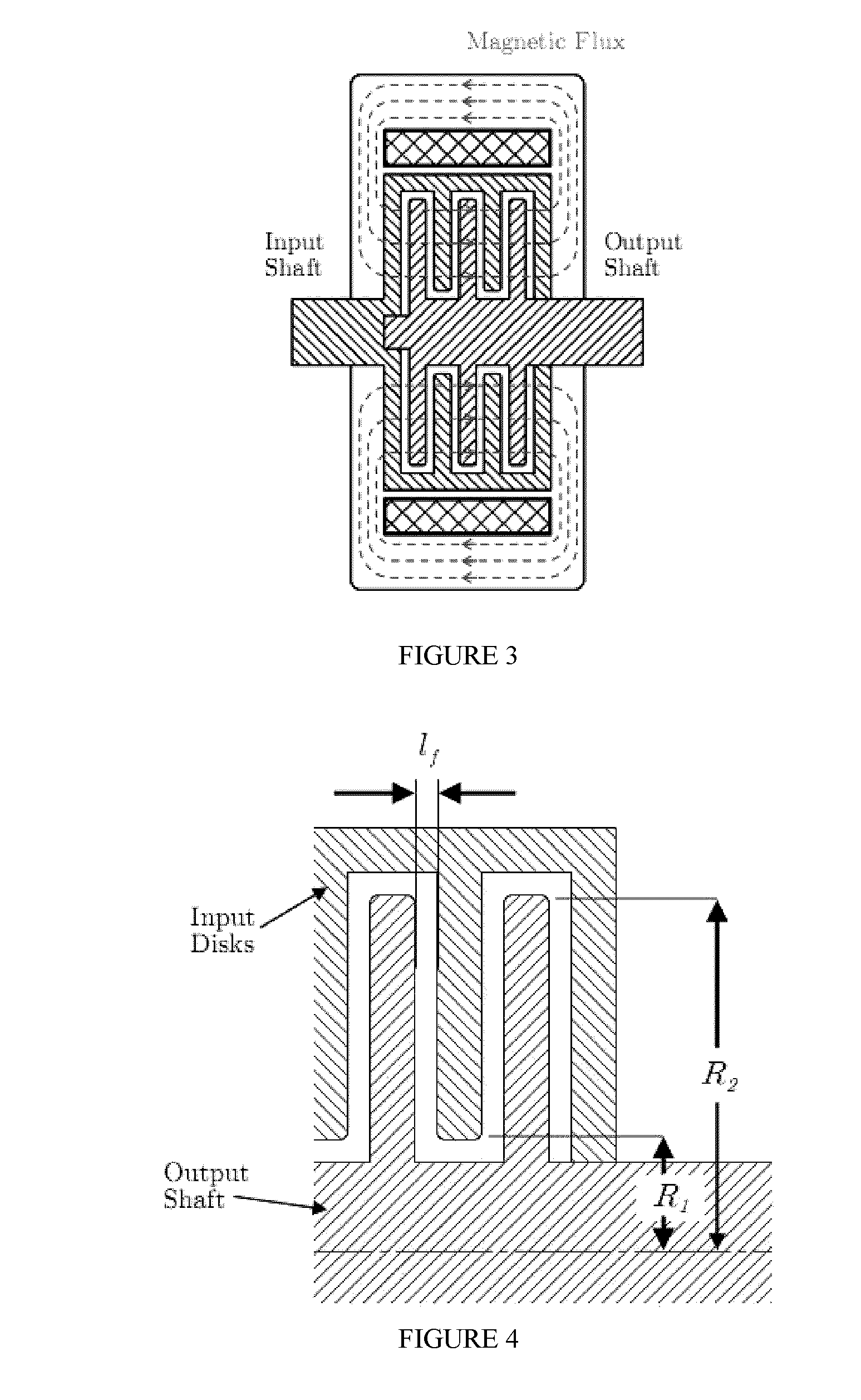
[0077]Using either MR or ER fluids, a clutch can be constructed such that the amount of torque it transmits can be controlled by the intensity or strength of an applied field. FIG. 2 is a cross-section of a multi-disk style MR fluid clutch while FIG. 3 illustrates the flux path within the MR fluid clutch. The input shaft breaks out into a set of input disks which are aligned in parallel to a set of output disks attached to the output sh...


PUM


Abstract

Systems and methods relating to a clutch system for use in controllably transmitting torque from an input shaft to an output shaft. The clutch system has a torque transmission fluid that has a viscosity that changes based on the strength of an electromagnetic field passing through the fluid. A number of sensors are placed at different radial locations on the torque transmission disks to detect the strength of the electromagnetic field. Based on the strength of the electromagnetic field, the amount of torque being transmitted from the input shaft to the output shaft can be adjusted. Also disclosed is a distributed actuation architecture that uses this clutch system. The distributed actuation architecture allows for the use of a single drive motor in conjunction with multiple instances of the clutch system to actuate a mechanical linkage, such as a robotic arm.

Description

TECHNICAL FIELD[0001]The present invention relates to torque transmission systems and, more particularly, it relates to a torque transmission system using a torque transmission fluid whose viscosity changes based on the intensity or strength of an electromagnetic field passing through the fluid.BACKGROUND OF THE INVENTION[0002]Increasingly, we are witnessing a growing number of developments in the field of robotics characterized by their intent to integrate man and machine in a safe and functional manner. The suitability of a manipulator to work in close proximity with humans is determined first by the level of safety it can guarantee towards its human counterparts. Guaranteeing safety is a difficult if not impossible exercise as we can rarely guarantee the dependability of the numerous components required to complete a modern manipulator. Add in the human factor, and our task becomes insurmountable.[0003]Thus, much focus has been centered on interactive robots which are expected to...

Claims


Application Information

Patent Timeline
IPC IPC(8): B25J18/00F16D27/00B25J17/00F16D27/12
CPCB25J19/06F16D37/008Y10T74/20305Y10T74/20329Y10T74/20317
Inventor SHAFER, ALEXKERMANI, MEHRDAD R.
Owner UNIV OF WESTERN ONTARIO
Why Eureka
Try Eureka