
Parking lot bumper inductive charger with automatic payment processing

a parking lot and inductive charging technology, applied in the field of electric vehicles, can solve problems such as user error, visual and physical clutter, and reduce space in already-congested locales

Active Publication Date: 2013-02-28
FARKAS MICHAEL
View PDF4 Cites 30 Cited by
  • Summary
  • Abstract
  • Description
  • Claims
  • Application Information

AI Technical Summary

Benefits of technology

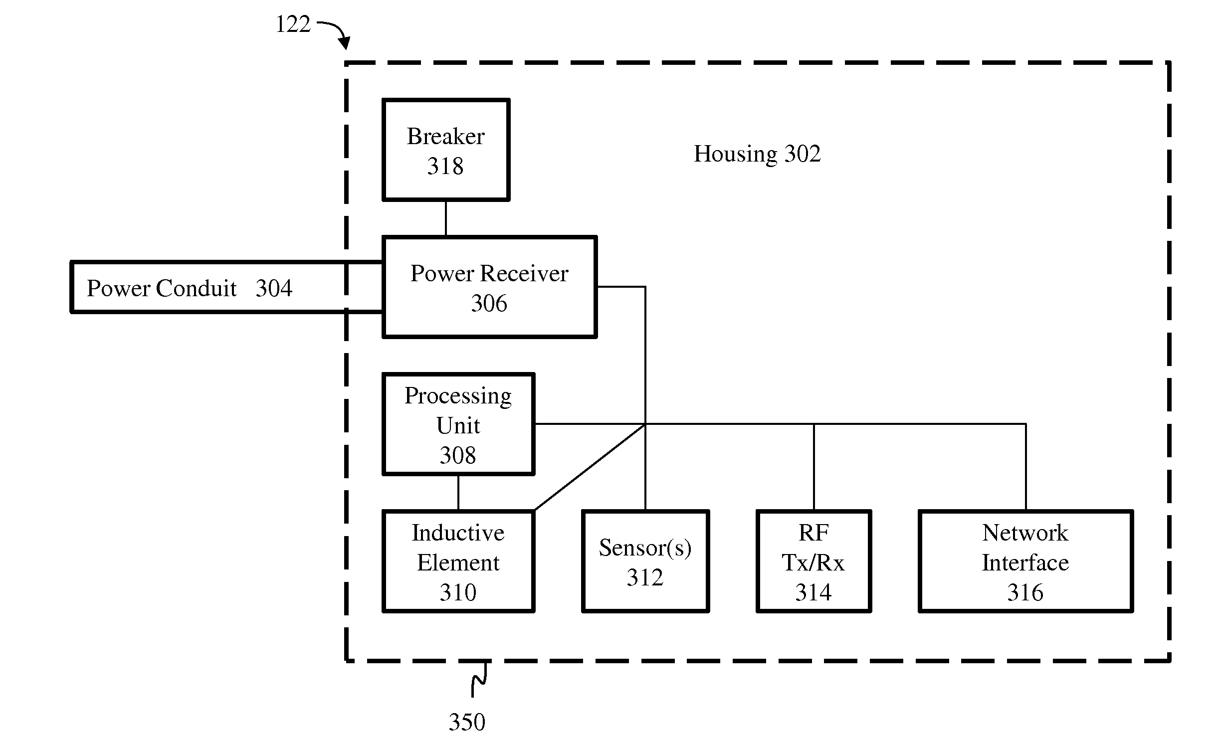
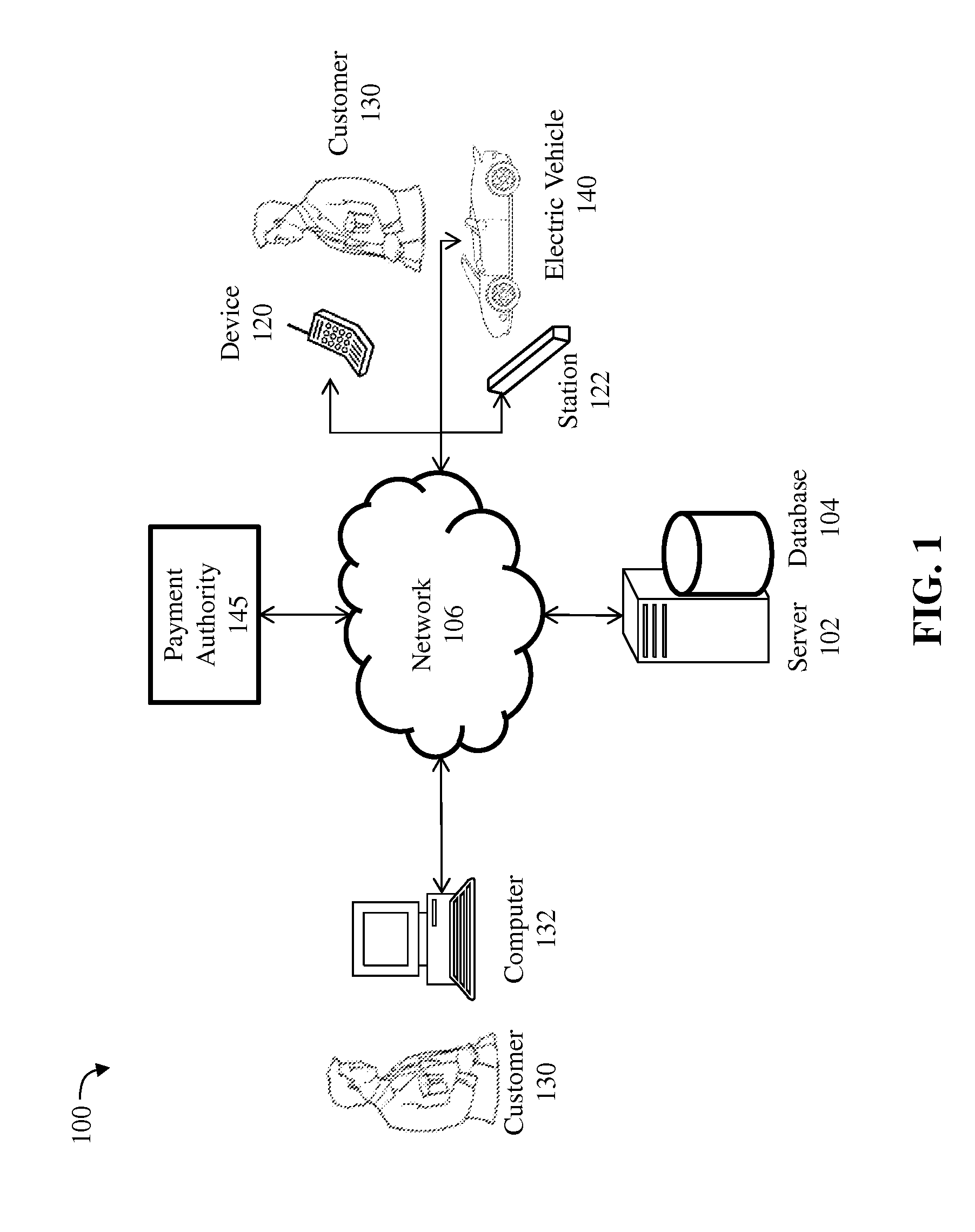
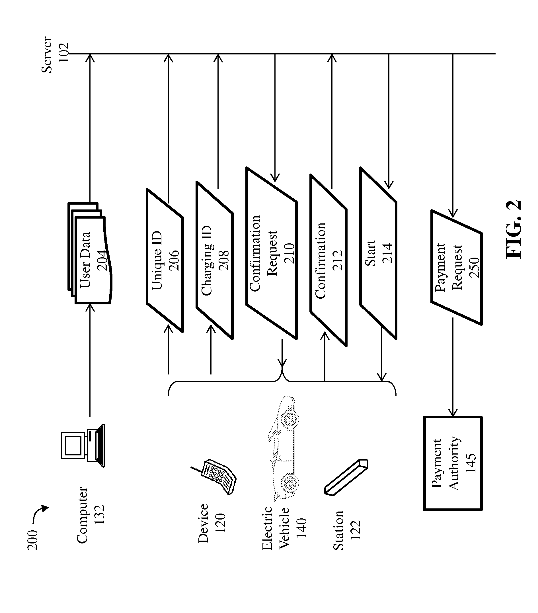
The patent describes a charging station for electric vehicles that can be paid for using a network. The charging station includes a housing with a planar element that provides a barrier for the electric vehicle's wheels, an inductive charging element, a sensor to detect the position of the vehicle, a radio frequency receiver to receive a unique identifier associated with the vehicle, and a network interface controller to transmit the identifier to a server and confirm the payment. A processor activates the charging element to provide charging to the vehicle after confirming the payment. This technology allows for easy charging of electric vehicles through a network.

Problems solved by technology

Unfortunately, installation of charging stations in these areas can produce visual and physical clutter and can reduce space in already-congested locales.
This can be cumbersome for some individuals, such as handicapped persons, and further opens the possibility of user error, which can produce a hazardous situation.
One of the drawbacks associated with this point-of-sale system is that it requires purchase cards to be swiped through a card reader or for the purchase card data to be input manually.
These constraints can be time consuming and tedious for drivers that are in a hurry and therefore limit the locations and circumstances where purchase cards can be used.

Method used


Image

  • Parking lot bumper inductive charger with automatic payment processing
  • Parking lot bumper inductive charger with automatic payment processing
  • Parking lot bumper inductive charger with automatic payment processing

Examples


Embodiment Construction

[0018]The present invention improves upon the problems with the prior art by providing inductive charging capabilities to electric vehicles in a user-friendly and safe manner. The present invention allows electric vehicle users to park their electric vehicles over a car charging station comprising a parking lot bumper and effectuate inductive charging of the electric vehicle's batteries without requiring the physical connection of any sockets or terminals. The present invention further facilitates the alignment of the electrical vehicle over the charging station by indicating to the user the placement of the vehicle over the charging station and by the sound and feel of the vehicle touching the parking bumper. Further, the parking lot bumper design of the present invention allows the device to be camouflaged, thereby reducing visual clutter. Also, the parking lot bumper design provides a small footprint, thereby reducing physical clutter and savings space in already-congested locale...


PUM


Abstract

A charging station for an electric vehicle, including payment processing over a communications network, is disclosed. The charging station includes a housing having an elongated shape emulating a parking bumper, including an elongated planar element disposed at an acute angle to a floor and designed to provide a barrier to wheels of the electric vehicle, an inductive charging element, a sensor for detecting a location of the electric vehicle in relation to the planar element of the charging station, a radio frequency receiver for receiving a signal including a unique identifier associated with the electric vehicle, a network interface controller configured for transmitting the unique identifier to a server and for receiving confirmation of payment for inductive charging provided to the electric vehicle and a processor configured for activating the inductive charging element to provide inductive charging to the electric vehicle responsive to receiving the confirmation of payment.

Description

CROSS-REFERENCE TO RELATED APPLICATIONS[0001]This patent application claims priority to provisional patent application No. 61 / 529,016 filed Aug. 30, 2011 and titled “Parking Lot Bumper Inductive Charger.” The content of provisional patent application No. 61 / 529,016 is hereby incorporated by reference in its entirety.STATEMENT REGARDING FEDERALLY SPONSORED RESEARCH OR DEVELOPMENT[0002]Not Applicable.INCORPORATION BY REFERENCE OF MATERIAL SUBMITTED ON A COMPACT DISC[0003]Not Applicable.FIELD OF THE INVENTION[0004]The present invention relates to the field of electric vehicles and, more specifically, the present invention relates to the field of inductive charging of battery units of electric vehicles.BACKGROUND OF THE INVENTION[0005]The green energy movement and dwindling fossil fuel supplies have spawned the commercial electric vehicle industry. Currently, charging stations are used to recharge the batteries of electric vehicles. A charging station usually comprises a standalone, ver...

Claims


Application Information

Patent Timeline
Patent Type & Authority Applications(United States)
IPC IPC(8): H02J7/00
CPCH02J7/00Y02T90/121B60L11/1846B60L11/1848B60L2230/16B60L2240/70B60L2250/12B60L2250/20Y02T90/169Y04S30/14H02J7/025H02J13/00H02J13/0006H02J2007/0001B60L3/003B60L3/0069B60L3/04B60L3/12B60L11/182B60L11/1824Y02T90/122Y02T10/7088Y02T10/7005Y02T90/125Y02T90/163Y02T90/14Y02T90/128G07F15/005Y02T10/7291B60L11/1833B60L53/30B60L53/36B60L53/65B60L53/665B60L53/305H02J7/00045B60L53/126B60L53/122H02J2310/48H02J50/10H02J50/80H02J50/90Y02T90/16Y02T10/7072Y02T10/72Y02T10/70Y02T90/12Y02T90/167H02J13/00022H02J13/00002Y04S40/126Y02B90/20H02J3/003
Inventor FARKAS, MICHAEL
Owner FARKAS MICHAEL
Learn More