Spectrometer

a spectrometer and optical power technology, applied in the field of substance analysis, can solve the problems of relatively slow process, relatively difficult quantitatively assessing non-linear interactive effects, and different optical power received by the substance, and achieve the effects of convenient precise timing, convenient use, and low cost of manufactur

Active Publication Date: 2013-02-28
GENIA PHOTONICS
View PDF2 Cites 11 Cited by
  • Summary
  • Abstract
  • Description
  • Claims
  • Application Information

AI Technical Summary

Benefits of technology

[0009]Advantageously, decoupling of the “delay” function and of the “dither” function in different elements creates a very flexible spectrometer that is relatively inexpensive to manufacture and relatively easy to use. This decoupling also facilitates precise timing for the reception of the first and second laser light pulses even when the first wavelength is varied rapidly.
[0010]For example, in some embodiments of the invention, consecutive trigger signals from the series of trigger signals are separated from each other by a respective inter-signal interval, the first wavelength being a predetermined function of the inter-signal interval. Synchronization of laser light pulse emissions and variations in the first wavelength are thus performed automatically and easily, ensuring good spectrum acquisition.

Problems solved by technology

A disadvantage of this method resides in that when the nonlinear effect is present, in other words when the substance is illuminated with first and second laser lights, the optical power received by the substance is different from the power received when only one of the laser lights is present.
Therefore, it is relatively difficult to quantitatively assess the non-linear interactive effects because of these power variations.
This process is typically relatively slow.

Method used


Image

  • Spectrometer
  • Spectrometer
  • Spectrometer

Examples


Embodiment Construction

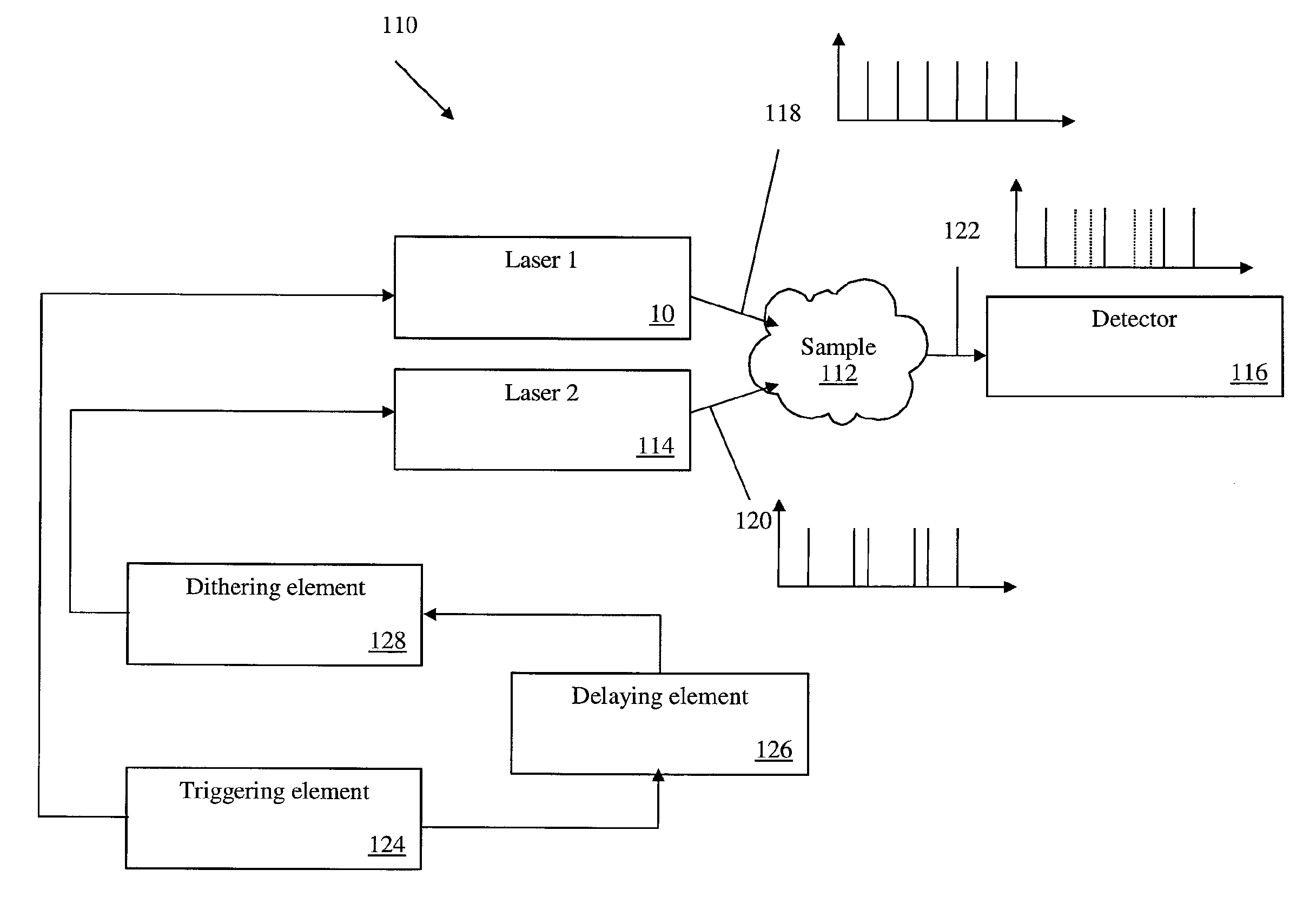
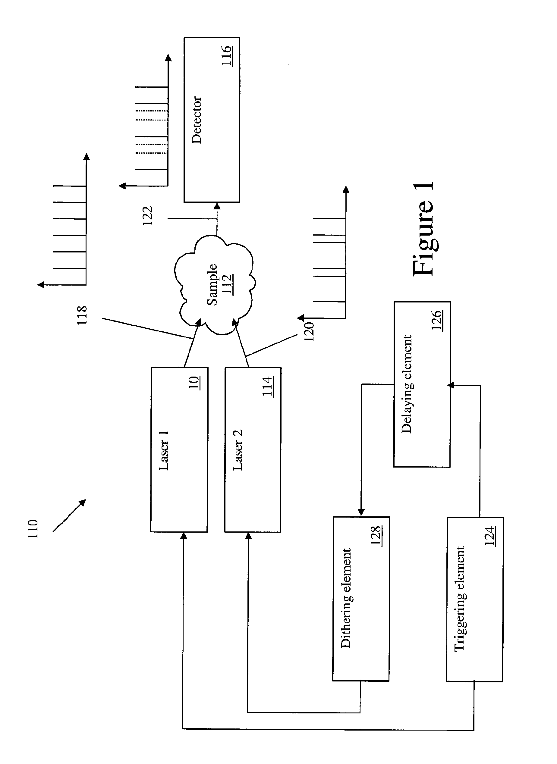
[0026]FIG. 1 illustrates a spectrometer 110 in accordance with an embodiment of the present invention. The spectrometer 110 is usable for characterizing a sample 112. Typically, the spectrometer 110 measures an optical nonlinear interaction in a sample 112 between light emitted by the spectrometer 110 and the matter contained in the sample 112. For example, a first laser 10, a second laser 114 and a light detector 116 are configured and positioned for performing a spectroscopy selected from the group consisting of Coherent anti-Stokes Raman Scattering (CARS) spectroscopy, Stimulated Raman Spectroscopy (SRS), sum frequency generation spectroscopy and difference frequency generation spectroscopy, among other possibilities.

[0027]The physical disposition of the first and second lasers 10 and 114 and of the light detector 116 relatively to each other and relatively to the sample 112 depends on the nature of the sample 112 and on the nature of the interaction between first and second lase...


PUM


Abstract

A spectrometer (110) including a triggering element (124) for generating a series of trigger signals, a first laser (10) for emitting toward a sample (112) a first laser light pulse (118) having a first wavelength in response to receiving each of the trigger signals, the first laser (10) being wavelength tunable so that the first wavelength is selectively variable; a second laser (114) for emitting toward the sample a second laser light pulse (120) having a second wavelength in response to receiving each of the trigger signals from the series of trigger signals; a dithering element (128) for selectively retarding transmission of the trigger signals to at least one of the first and second lasers such that the first and second laser light pulses (118, 120) are received at the sample substantially non-simultaneously; a delaying element (126) for retarding transmission of the trigger signals to at least one of the first and second lasers in a manner such that the first and second laser light pulses (118, 120) are received at the sample substantially simultaneously when the dithering element (128) is inactive state.

Description

[0001]The present application claims priority from U.S. Provisional Patent Application Ser. No. 61 / 272,496 filed on Sep. 30, 2009, the contents of which is incorporated herein by reference in its entirety.FIELD OF THE INVENTION[0002]The present invention relates to the general field of substance analysis, and is particularly concerned with a method and device for measuring optical nonlinear interactions in a sample.BACKGROUND[0003]Many types of spectroscopies require that a sample to characterize be illuminated with light having two different wavelengths simultaneously. Then, the interaction of the sample with this simultaneous illumination is characterized.[0004]Characterization of optical nonlinearities in substances is of great importance for many applications. For example, in Stimulated Raman Scattering (SRS), a substance is illuminated with pulses of laser light having two different wavelengths. Laser light at a first wavelength is pulsed at a first pulse frequency. Laser light...

Claims


Application Information

Patent Timeline
Patent Type & Authority Applications(United States)
IPC IPC(8): G01J3/10G01J3/44
CPCG01J3/10G01J3/44H01S3/2391H01S3/1305H01S3/2383H01S3/10046
Inventor VILLENEUVE, ALAINBURGOYNE, BRYANCOTE, DANIELBEGIN, STEVE
Owner GENIA PHOTONICS
Why Eureka
Try Eureka