Photonic millimeter-wave generator

a generator and millimeter wave technology, applied in electromagnetic transmission, electrical equipment, transmission, etc., can solve the problems of incomplete dispersion compensation, inability to complete dispersion compensation, and inability to complete dispersion compensation, and achieve the effect of extending the transmission distan

Inactive Publication Date: 2013-02-28
NATIONAL TSING HUA UNIVERSITY
View PDF5 Cites 19 Cited by
  • Summary
  • Abstract
  • Description
  • Claims
  • Application Information

AI Technical Summary

Benefits of technology

[0011]Another object of the present invention is to provide a photonic millimeter-wave generator capable of generating short optical pulses (less than 1 pico-second duration for each optical pulse), ultra-high repetition-rate optical pulse trains, and delivering the optical pulses over a fiber without distortion.
[0012]A further object of the present invention is to provide a method for delivering optical signal over an optical fiber in which the dispersion is eliminated so that the use of dispersion compensating fiber is not required.

Problems solved by technology

Further, while optical pulses are transmitted over a fiber, distortion is inevitable.
However, due to the broad optical bandwidth of ultra-short pulses, complete dispersion compensation is essential and remains a challenging task.
Further, highly stable ultrahigh-rate short optical pulses may not be generated easily through conventional laser system or direct modulation techniques.

Method used


Image

  • Photonic millimeter-wave generator
  • Photonic millimeter-wave generator
  • Photonic millimeter-wave generator

Examples


embodiment 1

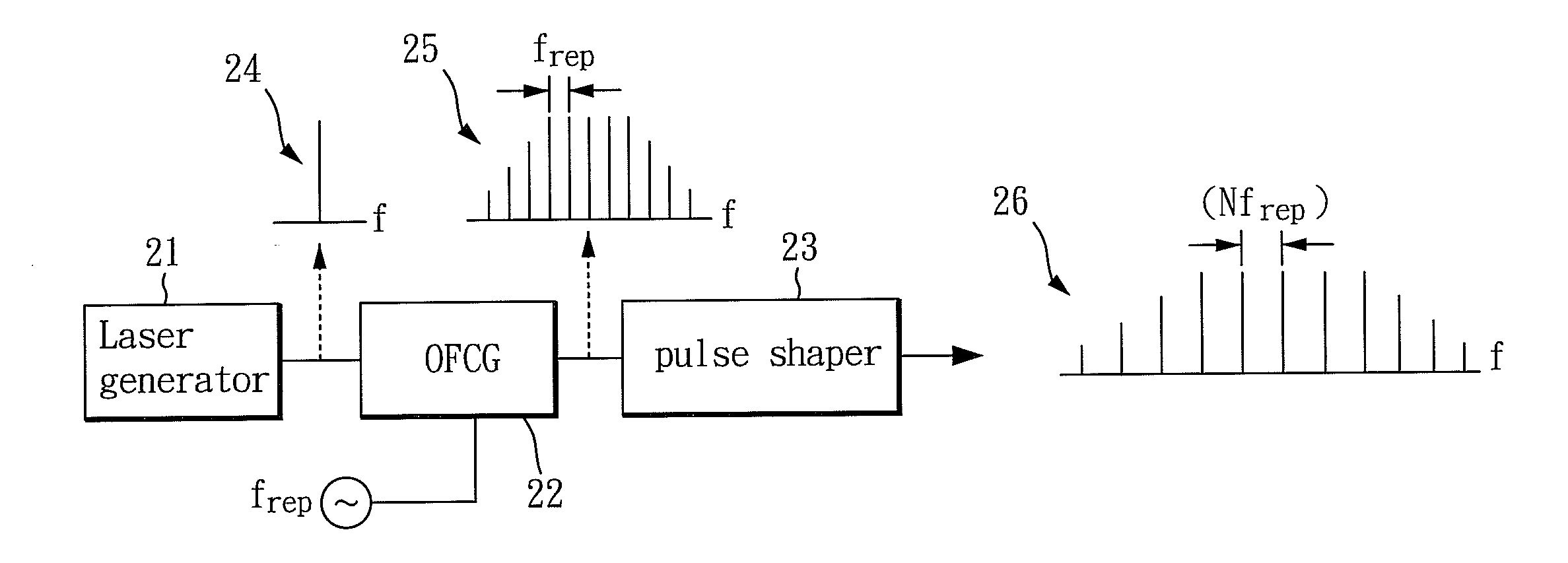
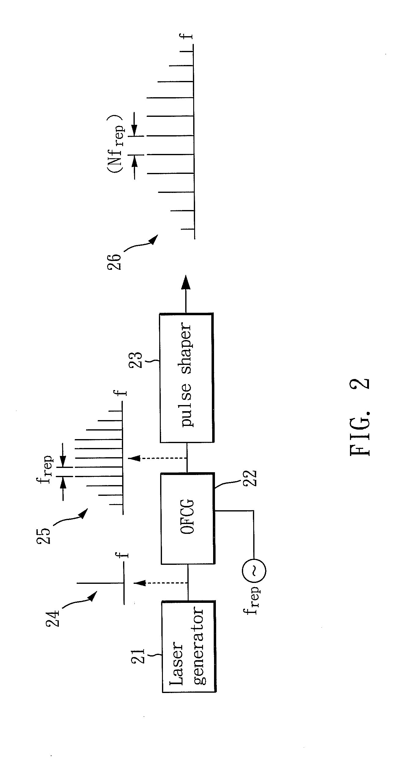
[0025]Embodiment 1 of the present invention is disclosed for generating extremely short and ultra high repetition-rate optical pulses. Please refer to FIG. 2, which is a schematic view illustrating the photonic millimeter-wave generator in accordance with the first embodiment of the present invention. As shown in FIG. 2, the photonic millimeter-wave generator of the present invention comprises: a laser generator 21, an optical frequency comb generator 22 (the optical frequency comb generator in the following specification is abbreviated as OFCG), and a pulse shaper 23. The laser generator 21 of this embodiment is preferred to be a continuous wave laser generator (CW laser generator) which generates a first optical signal 24. Further, the first optical signal is a narrow-linewidth CW laser and, as shown in FIG. 2, the first optical signal 24 contains only one single frequency component.

[0026]The optical frequency comb generator 22 is coupled with the laser generator 21 for receiving ...

embodiment 2

[0029]Embodiment 2 of the present invention is disclosed for generating extremely short and ultra high repetition-rate optical pulses and further, to deliver the abovementioned optical pulses over a fiber without dispersion compensating fiber.

[0030]Please refer to FIG. 3, which is a schematic view illustrating the photonic millimeter-wave generator in accordance with the second embodiment of the present invention. As shown in FIG. 3, the photonic millimeter-wave generator of the present invention comprises: a laser generator 31, an optical frequency comb generator 32, and a pulse shaper 33. The laser generator 31 of this embodiment is preferred be a continuous wave laser generator (CW laser generator) which generates a first optical signal 34. Further, the first optical signal is a narrow-linewidth CW laser and, as shown in FIG. 3, the first optical signal 34 contains only one single frequency component.

[0031]The optical frequency comb generator 32 is coupled with the laser generato...


PUM


Abstract

A photonic millimeter-wave generator capable of combining wired and wireless communication facilities to further elongate the transmission distance comprises a laser generator for generating a first optical signal; an optical frequency comb generator coupled with the laser generator; and a pulse shaper coupled with the optical frequency comb generator. The optical frequency comb generator receives the first optical signal generated by the laser generator and outputs a second optical signal. The second optical signal contains multiple frequency components and is sent to the pulse shaper. The pulse shaper adjusts the amplitude and phase of the second optical signal and then outputs the signal as a third optical signal.

Description

BACKGROUND OF THE INVENTION[0001]1. Field of the Invention[0002]The present invention relates to a photonic millimeter-wave generator and, more particularly, to a photonic millimeter-wave generator capable of combining wired and wireless communication facilities to further elongate the transmission distance.[0003]2. Description of Related Art[0004]The generation of high repetition-rate optical pulses is playing an important role in high-speed optical fiber and microwave photonics systems. In particular, millimeter-wave (MMW) carriers in the W-band (75-110 GHz) or above are essential to meet the recent demand of gigabits wireless access applications. Due to the relatively higher propagation loss of W-band signal than that of RF bands in free space, radio-over-fiber technology provides an efficient and cost effective way to distribute photonic MMW waveforms from the central office to the base station. Such a scheme has been recently adopted for photonic-assisted MMW carrier generation...

Claims


Application Information

Patent Timeline
Patent Type & Authority Applications(United States)
IPC IPC(8): H04B10/04
CPCH04B2210/006H04B10/25754
Inventor HUANG, CHEN-BINSHI, JIN-WEIPAN, CI-LING
Owner NATIONAL TSING HUA UNIVERSITY
Why Eureka
Try Eureka