Supercharge Your Innovation With Domain-Expert AI Agents!

Truss and rebar reinforced concrete structures

Inactive Publication Date: 2013-03-07
NUCOR CORP
View PDF8 Cites 1 Cited by
  • Summary
  • Abstract
  • Description
  • Claims
  • Application Information

AI Technical Summary

Benefits of technology

The patent text explains the problems with using standees to support reinforced concrete structures and proposes the use of trusses as an alternative. The technical effects of using trusses include improved tolerances, easier installation, reduced labor costs, improved quality assurance, and reduced risk of danger. These benefits make trusses a safer and more cost-effective alternative to standees, which are prone to uneven stresses, deflections, and conformability issues. The trusses can be interchanged throughout various similar support structures, making assembly faster and more accurate. Additionally, trusses provide continuous support under the mat, leading to less need for additional screeding and labor.

Problems solved by technology

While rebar structures made from mats and standees usually have low material costs in most applications, there are a number of issues associated with the using these types of rebar structures, such as large tolerances, dangerous configurations, lack of conformability, quality assurance issues, high labor costs, and potential increased material costs in large applications, etc.
The tolerances issues associated with producing the standees (e.g. plus or minus an inch) are such that additional spacers may be necessary in order to secure the standees to the mats at the proper heights and to allow the mats to rest at the required positions to produce the desired surfaces of the reinforced concrete structure after the concrete is poured.
These steps increase the labor costs associated with positioning the mats in the required locations.
Furthermore, while standees are typically used in applications in which they are less than four feet tall, in applications that require standees that are greater than four feet tall the tolerances issues may be amplified.
Therefore, engineers are often required to design and approve the mats and standees that are used when the standees are greater than four feet tall, which again increases the costs.

Method used


Image

  • Truss and rebar reinforced concrete structures
  • Truss and rebar reinforced concrete structures
  • Truss and rebar reinforced concrete structures

Examples


Embodiment Construction

[0047]Embodiments of the present invention will now be described more fully hereinafter with reference to the accompanying drawings, in which some, but not all, embodiments of the invention are shown. Indeed, the invention may be embodied in many different forms and should not be construed as limited to the embodiments set forth herein; rather, these embodiments are provided so that this disclosure will satisfy applicable legal requirements. Like numbers refer to like elements throughout.

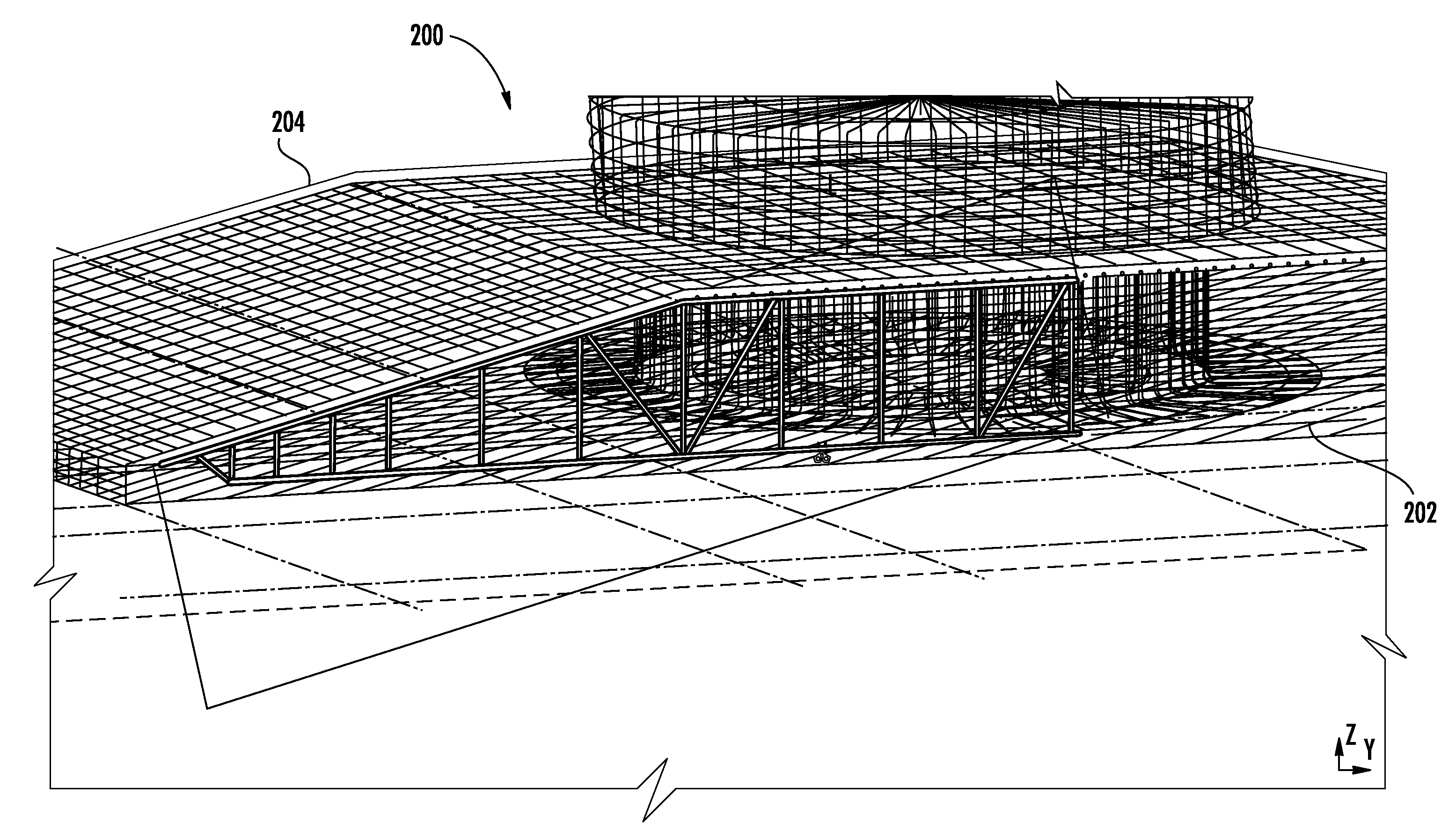
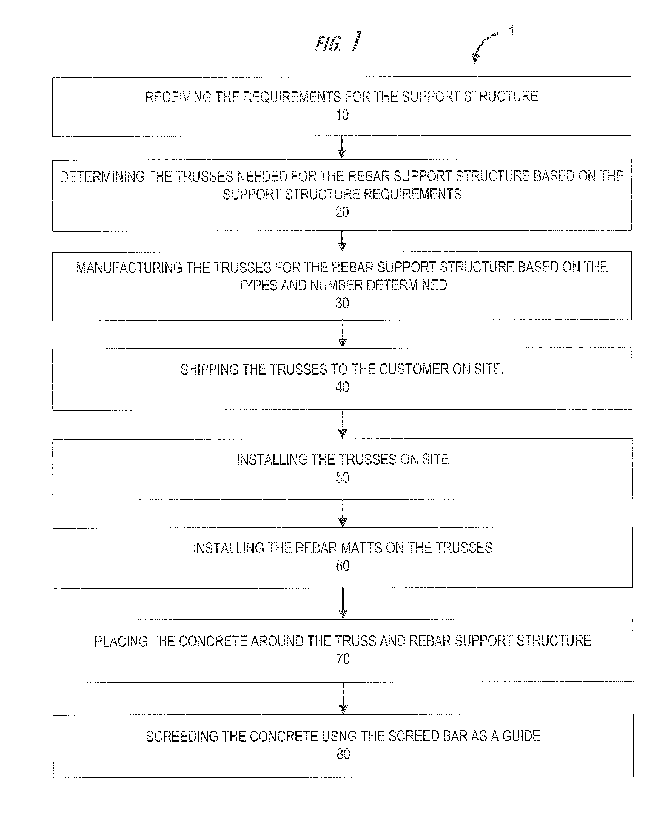
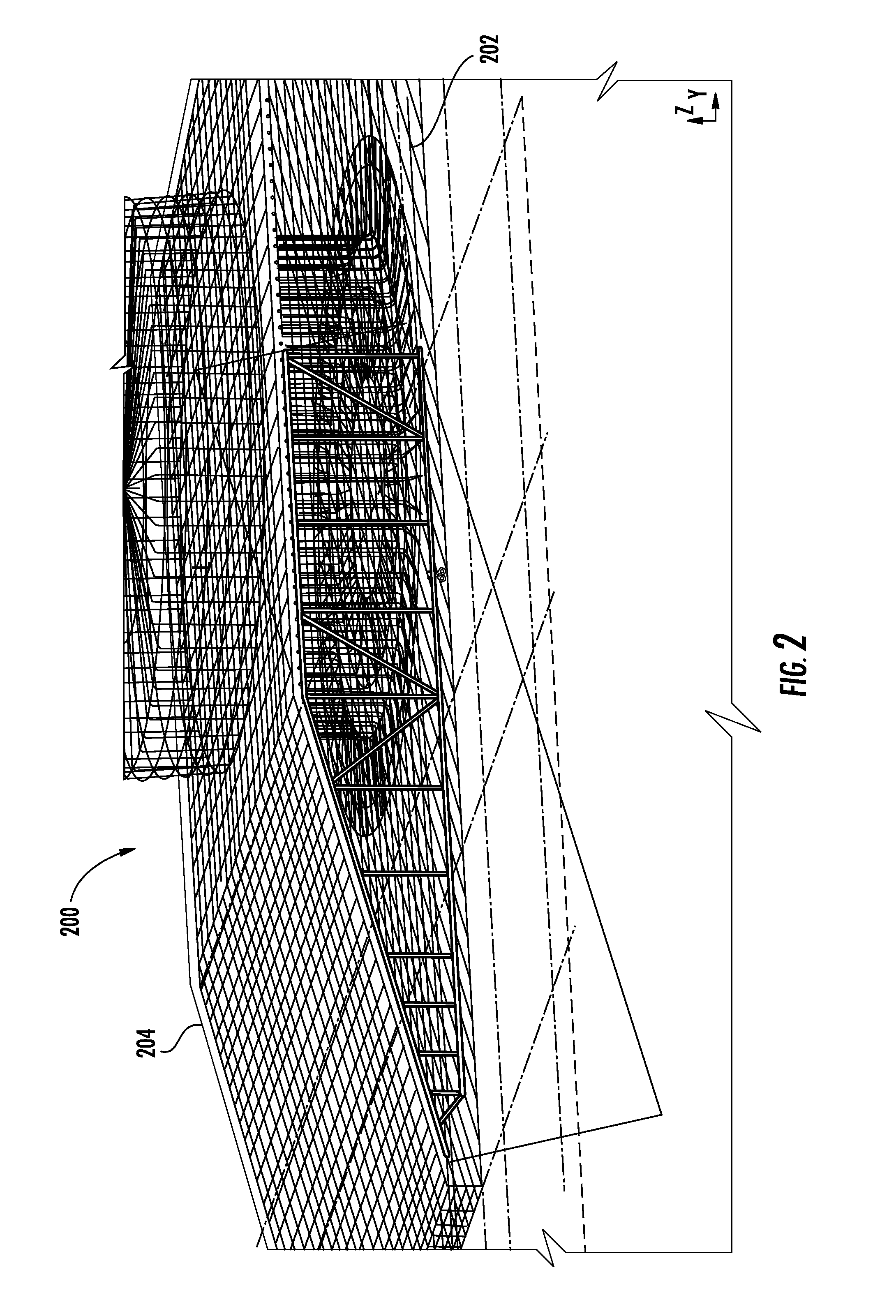
[0048]As illustrated by block 10 in FIG. 1, the manufacturing and installation process 1 comprises receiving requirements for a reinforced concrete structure. The requirements may be, but not limited to, the dimensions of the reinforced concrete structure, such as the surface contours (e.g. bends, curved surfaces), the load forces, the locations of loading, etc. For example, in one embodiment of the invention the reinforced concrete structure may be a bridge abutment or girder. In other embodiments ...


PUM


Abstract

Embodiments of the invention comprise apparatuses and methods of manufacturing and installing reinforced concrete structures. The reinforced concrete structures utilize trusses and rebar to form a support structure. A screed guide bar is removeably coupled to the support structure. Concrete is supplied to the support structure, and screeding occurs to form the reinforced concrete structure from the support structure (e.g., rebar mats and trusses) and concrete. The use of trusses and the screed guide bar allow for the formation of a reinforced concrete structure without the need for using spacers and standees to position the mats, or performing position checks to determine the position of the concrete during screeding. The screed bar guide allows workers to quickly form the desired surface of the reinforced concrete structure, remove the screed bar, and fill any void left by the screed bar, as necessary.

Description

CLAIM OF PRIORITY UNDER 35 U.S.C. §119[0001]The present application for a patent claims priority to Provisional Application No. 61 / 505,939 entitled “Truss and Rebar Reinforced Concrete Structures” filed Jul. 8, 2011 and assigned to the assignees hereof and hereby expressly incorporated by reference herein.BACKGROUND[0002]Reinforced concrete is used in many different applications for supporting various types of loads. The reinforced concrete typically utilizes rebar structures on which concrete is poured to form the concrete structures. The present invention relates to apparatuses and methods that have improvements over the typical reinforced concrete structures and methods of installing the typical reinforced concrete structures.BRIEF SUMMARY OF THE INVENTION[0003]This invention relates generally to support structures, and more particularly embodiments of the invention relate to truss and rebar configurations utilized in reinforced concrete structures for various support application...

Claims


Application Information

Patent Timeline
IPC IPC(8): E04C5/00E04G21/02E04F21/00
CPCE04F21/00E04G21/02E04C5/18E04C5/0631E04C5/065E04C5/0604
Inventor DAYTON, LIONEL EDWARD
Owner NUCOR CORP
Features
  • R&D
  • Intellectual Property
  • Life Sciences
  • Materials
  • Tech Scout
  • Unparalleled Data Quality
  • Higher Quality Content
  • 60% Fewer Hallucinations
Learn More