Steam injected gas turbine engine

a gas turbine engine and steam injection technology, applied in the direction of machines/engines, mechanical equipment, lighting and heating apparatus, etc., can solve the problems of difficult control of steam placement to the conditions required for combustion and cooling, and achieve the effect of improving the flexibility of steam injection placemen

Active Publication Date: 2013-03-07
ROLLS ROYCE PLC
View PDF3 Cites 4 Cited by
  • Summary
  • Abstract
  • Description
  • Claims
  • Application Information

AI Technical Summary

Benefits of technology

[0006]It would be desirable to improve the flexibility of placement of steam injection in advanced cycle engines. In particular, steam injected into ...

Problems solved by technology

In particular, steam injected into the vicinity of the outlet of the compressor section can ...

Method used


Image

  • Steam injected gas turbine engine
  • Steam injected gas turbine engine
  • Steam injected gas turbine engine

Examples


Embodiment Construction

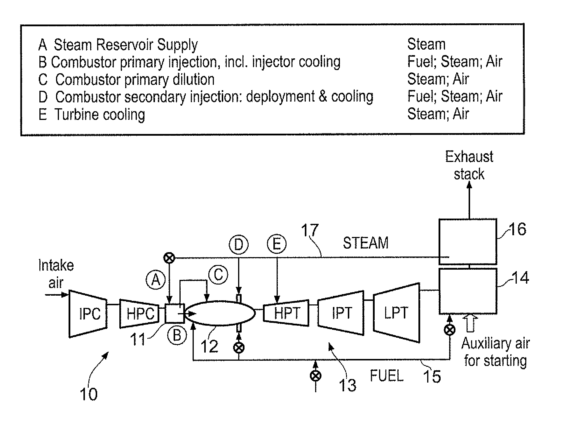
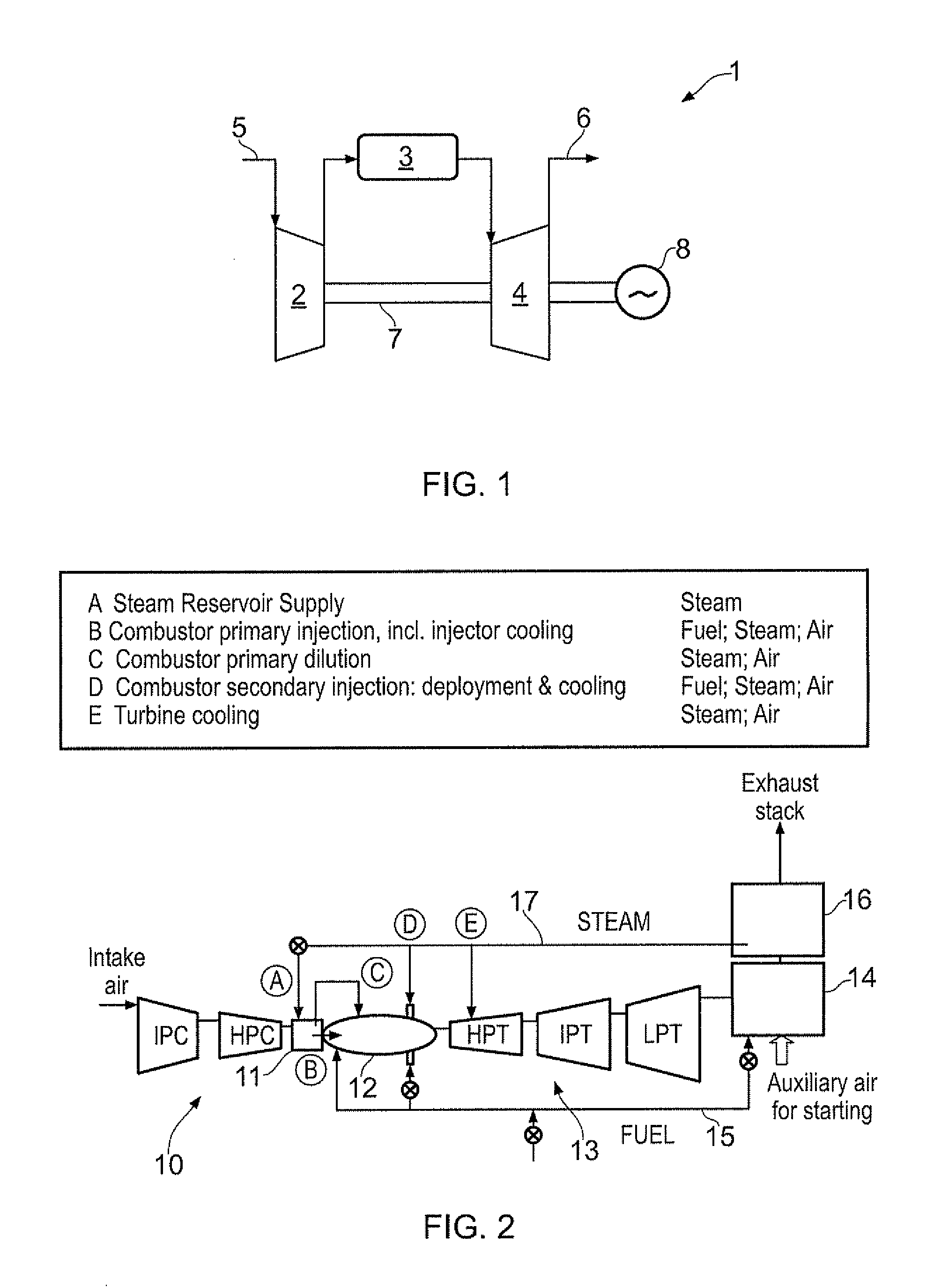
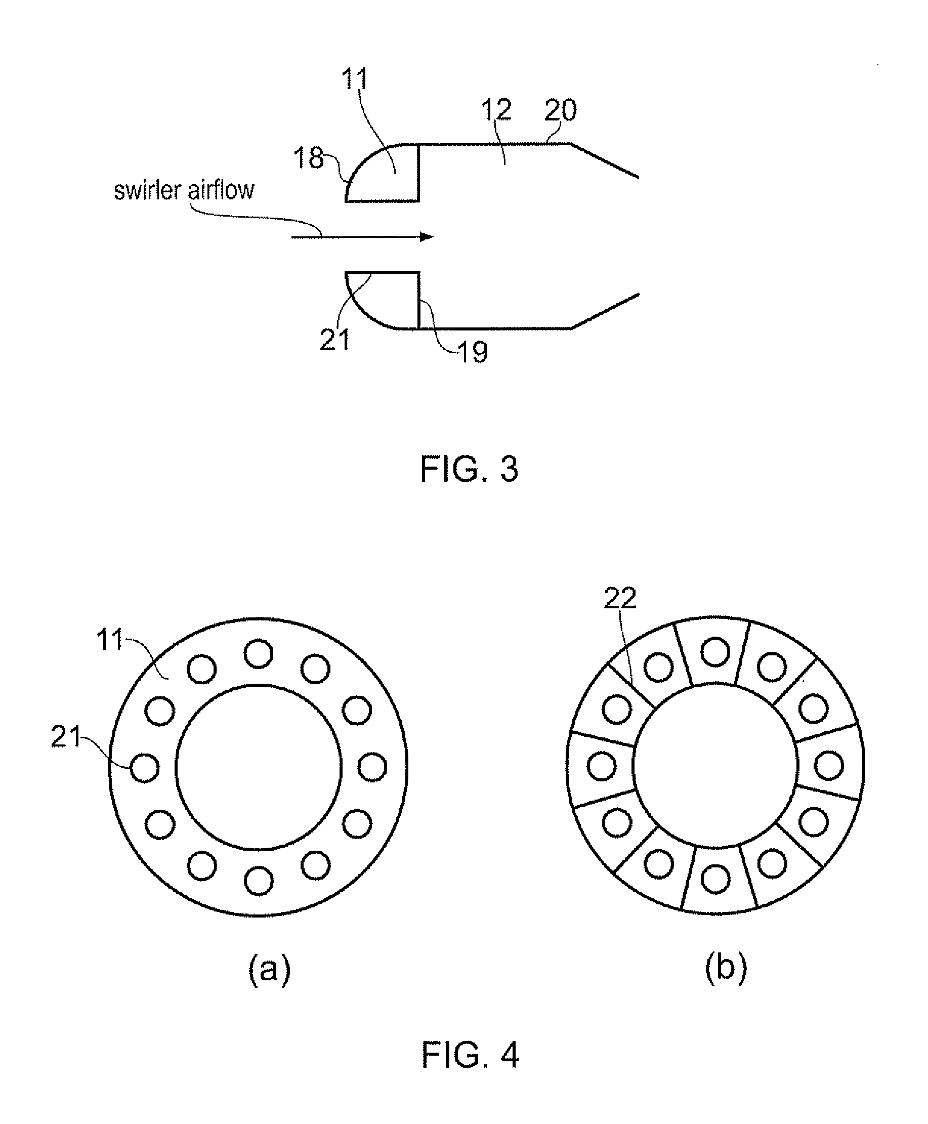
[0043]FIG. 2 shows schematically an industrial gas turbine engine according to the present invention, and indicates the main feed routes for steam and fuel. The engine comprises, in flow series through the engine: a compressor section 10 comprising an intermediate pressure compressor (IPC) and a high pressure compressor (HPC); combustor comprising a steam reservoir 11 and a combustion chamber 12; a turbine section 13 comprising a high pressure turbine (HPT), an intermediate pressure turbine (IPT) and a low pressure turbine (LPT); and an exhaust duct burner 14. The IPC and IPT are connected by a shaft, and the HPC and HPT are connected by another, coaxial, shaft. The LPT drives a generator (not shown). A fuel feed 15 supplies fuel to primary and secondary injection positions of the combustion chamber. The fuel feed also supplies fuel to the exhaust duct burner. Heat is extracted from the burner by a boiler 16 and used to generate steam, which is sent to a steam feed 17. Some of the s...


PUM


Abstract

A gas turbine engine has in flow series: a compressor section, a combustion chamber, and a turbine section. The engine further has a steam generator. The combustion chamber has a steam reservoir located at the upstream end thereof. The steam reservoir receives steam from the steam generator, and delivers the received steam into a combustion zone of the combustion chamber.

Description

FIELD OF THE INVENTION[0001]The present invention relates to a gas turbine engine in which steam is injected into a combustion chamber.BACKGROUND OF THE INVENTION[0002]FIG. 1 shows schematically a conventional industrial gas turbine engine 1 which comprises, in flow series through the engine, a compressor section 2, a combustor 3, and a turbine section 4. The engine works in a conventional manner so that air entering an intake 5 of the engine forms a flow into the compressor section, which compresses the flow before delivering the compressed air into the combustor where it is mixed with fuel and the mixture combusted. The resultant hot combustion products then expand through and thereby drive the turbine section before being exhausted through an exhaust 6. The turbine section is mounted on a shaft or coaxial shafts 7 with the compressor section and a generator 8. Power extracted from the working gas by the turbine section drives the compressor section and the generator.[0003]Steam i...

Claims


Application Information

Patent Timeline
IPC IPC(8): F02C3/30
CPCF02C3/30F02C3/305F02C6/18F05D2270/082F23R3/04F23R3/283F23L7/005
Inventor FLETCHER, PAULGRAHAM, ANDREW C.MORAN, JOHNNEESON, CHRISTOPHER
Owner ROLLS ROYCE PLC
Why Eureka
Try Eureka