Permanent magnet motors and methods of assembling the same

a permanent magnet, rotor motor technology, applied in the direction of stator/rotor body manufacturing, magnetic circuit rotating parts, magnetic circuit shape/form/construction, etc., can solve the problems of unfavorable motor performance, unfavorable motor performance, and undesirable torsional ripple of torque resulting from the magnetic interaction between the rotor and the stator, so as to achieve the effect of increasing the motor performan

Inactive Publication Date: 2013-03-07
FASCO AUSTRALIA PTY LTD +1
View PDF6 Cites 23 Cited by
  • Summary
  • Abstract
  • Description
  • Claims
  • Application Information

AI Technical Summary

Benefits of technology

[0006]A permanent magnet rotor may include permanent magnets embedded within a rotor core. Such a rotor may be referred to as an interior permanent magnet rotor. Slots are formed within the rotor core and magnets are inserted into the slots. Positioning the permanent magnets close to the outer surface of the rotor core increases motor performance. However, the rotor core must be configured to provide adequate mechanical support for the permanent magnets. The magnets, as well as the surrounding structures, are subject to various forces arising from thermal expansion, rotation, and residual forces caused by the manufacturing process, such as distortion due to welding.

Problems solved by technology

As such, the brushless motors are subject to many operating conditions.
In such a motor, the torque resulting from the magnetic interaction between the rotor and stator may contain an undesirable torsional ripple, either resulting from the current in the windings, or simply from the interaction of the permanent magnets and the stator, present in an unpowered machine, which is known as detent or cogging torque.
In addition, there may be radial forces between the rotor and stator which cause objectionable noise.
More specifically, the passing of the rotor magnets through the open area between stator teeth, coupled with the attraction to and repulsion from the solid teeth of the stator causes vibration, cogging torque, torque pulsation and potentially motor noise, an amount of which may be objectionable to a user.
Audible motor noise is unacceptable in many applications.
In such applications these torque pulses and the effects of cogging may result in operational issues and / or acoustical noise that can be objectionable to an end user of the motor.
However, semi-closed stator slots typically increase the complexity and expense of coil winding machinery.
However, stators that incorporate semi-closed slots are more difficult to fabricate, and the area available for the copper wire windings that can be inserted or wound into such slots is limited.
The magnets, as well as the surrounding structures, are subject to various forces arising from thermal expansion, rotation, and residual forces caused by the manufacturing process, such as distortion due to welding.

Method used


Image

  • Permanent magnet motors and methods of assembling the same
  • Permanent magnet motors and methods of assembling the same
  • Permanent magnet motors and methods of assembling the same

Examples


Embodiment Construction

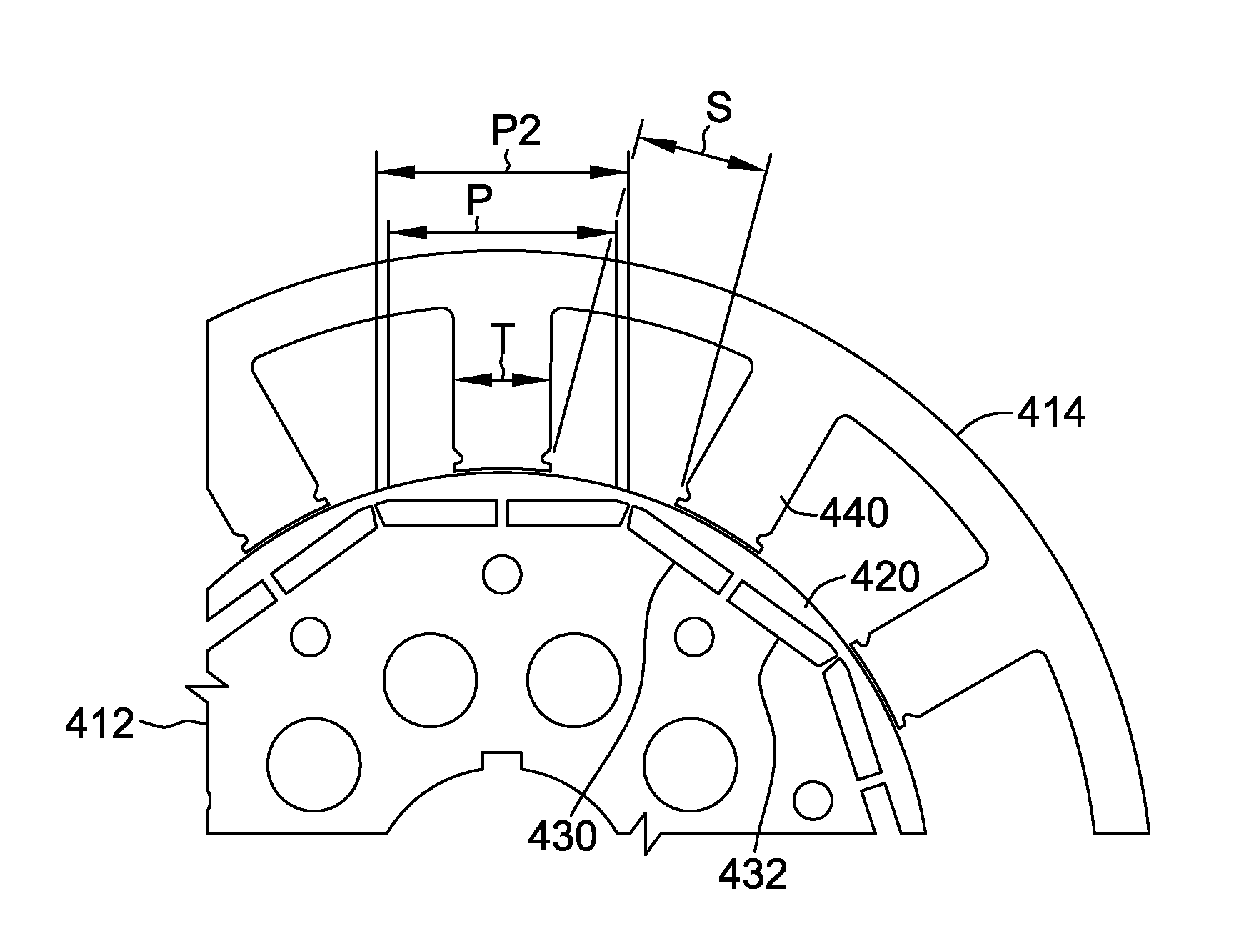
[0019]Torque generated by the magnetic interaction between a rotor and a stator may contain an undesirable cogging and / or commutation torque component that may be transmitted to the motor shaft, and then to a work component, possibly resulting in objectionable acoustical noise and vibration. Furthermore, radial forces on a rotor within a motor containing an open slot stator may also cause objectionable noise. Described herein are methods and systems related to determining a stator skew based on the number of stator teeth / slots and rotor poles, configuring an interior permanent magnet rotor, and positioning of a magnetic or semi-magnetic wedge between the skewed stator teeth. These methods and systems improve motor performance and / or reduce noise and vibration.

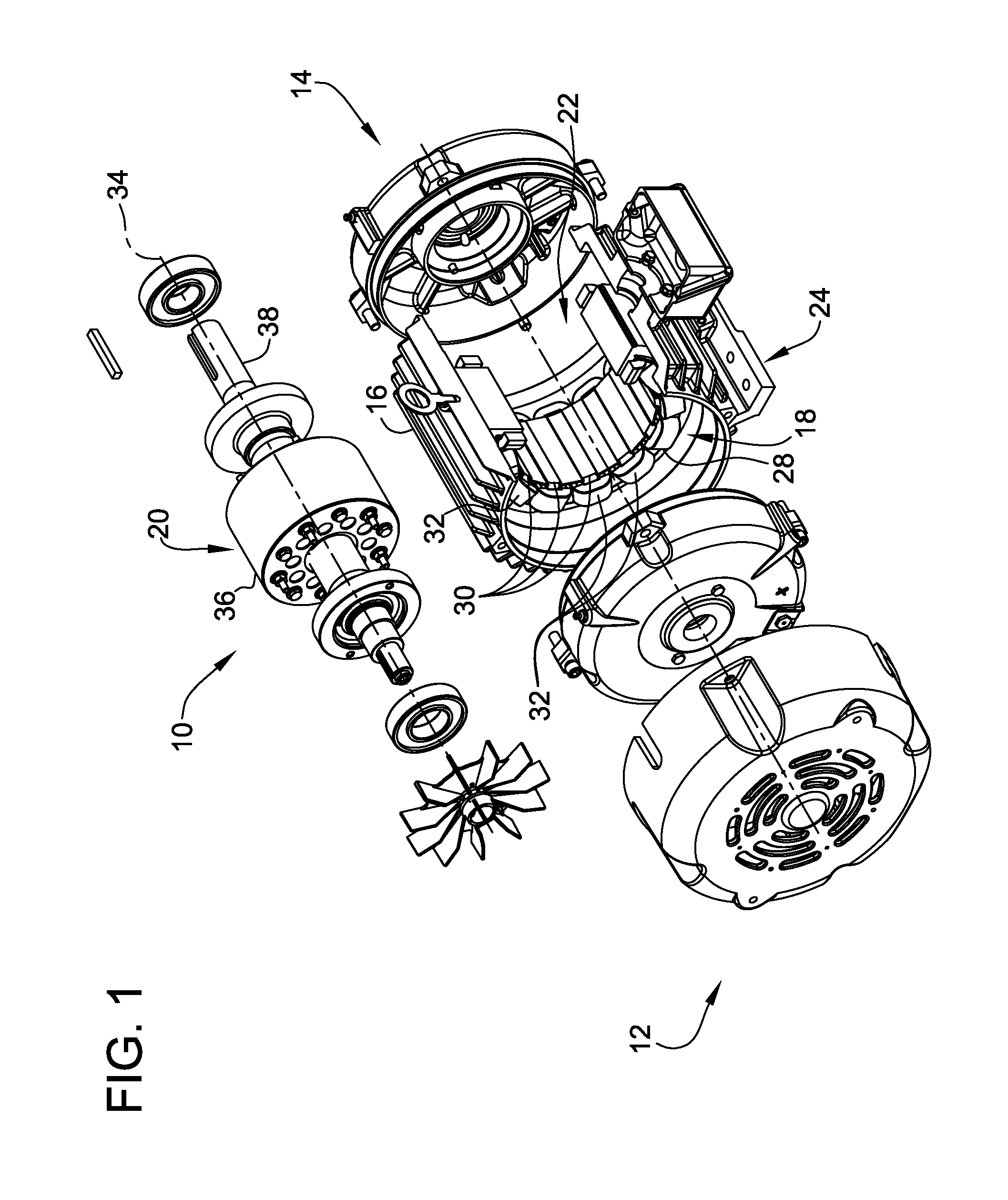
[0020]FIG. 1 is an exploded cutaway view of an exemplary electric machine 10. Although electric machine 10 is referred to herein as an electric motor, electric machine 10 can be operated as either a generator or a motor. Electr...


PUM

PropertyMeasurementUnit
resultant skew angleaaaaaaaaaa
saturation flux densityaaaaaaaaaa
flux densityaaaaaaaaaa

Abstract

A method for manufacturing an interior permanent magnet motor is described herein. The method includes providing a plurality of permanent magnets and fabricating a ferromagnetic rotor core configured to accept the permanent magnets therein such that the ferromagnetic material utilized to retain the permanent magnets within the rotor core operates to concentrate and steer the flux from one or more of the permanent magnets to a stator tooth. The method also includes positioning the rotor core with the permanent magnets therein with respect to a wound, open slot stator core.

Description

BACKGROUND[0001]This disclosure relates generally to permanent magnet rotor motors, and more particularly, to methods and systems for reducing noise and cogging torque in motors incorporating a permanent magnet rotor.[0002]Certain permanent magnet rotor motors are sometimes referred to as brushless motors. Brushless motors include both brushless AC motors and brushless DC motors. Brushless motors are used in a wide variety of systems operating in a wide variety of industries. As such, the brushless motors are subject to many operating conditions. In such a motor, the torque resulting from the magnetic interaction between the rotor and stator may contain an undesirable torsional ripple, either resulting from the current in the windings, or simply from the interaction of the permanent magnets and the stator, present in an unpowered machine, which is known as detent or cogging torque. In addition, there may be radial forces between the rotor and stator which cause objectionable noise.[...

Claims


Application Information

Patent Timeline
Patent Type & Authority Applications(United States)
IPC IPC(8): H02K1/27H02K15/02
CPCH02K21/16H02K29/03Y10T29/49012H02K2201/06H02K2213/03H02K1/276
Inventor PATTERSON, DEAN JAMESSTRETZ, STEVENSTADLER, WILLIAMYEADON, ALAN W.
Owner FASCO AUSTRALIA PTY LTD
Why Eureka
Try Eureka