
System and method for situational awareness and target cueing

a situational awareness and target cueing technology, applied in the field of night vision systems, can solve the problems of less attenuation of infrared thermal imaging, user's inability to see through smoke and heavy sand, and inability to see a person hidden under camouflage, so as to reduce the contribution of lll sensor, reduce the number of false threats, and high sa resolution and capability

Active Publication Date: 2013-03-07
BAE SYST INFORMATION & ELECTRONICS SYST INTERGRATION INC
View PDF5 Cites 7 Cited by
  • Summary
  • Abstract
  • Description
  • Claims
  • Application Information

AI Technical Summary

Benefits of technology

The present invention is a system and method that can provide improved situational awareness and weapon target cueing in low light or no light situations. The system utilizes a thermal sensor and a low light level sensor to maintain high resolution in low light levels. The system can adapt to dynamic scenes and make use of metrics provided by the thermal sensor to enhance the SA capability in dark scenarios. The invention also utilizes spatial frequency based histogram thresholding techniques to mask potential threats from background. Overall, the invention provides better performance than existing low light level sensor technology and is useful for military operations in low light to no light situations.

Problems solved by technology

In low light imaging, user cannot see through smoke and heavy sand storms and cannot see a person hidden under camouflage.
Infrared thermal imaging is less attenuated by smoke and dust and a drawback is that they do not have sufficient resolution and sensitivity to provide acceptable imagery of a scene.
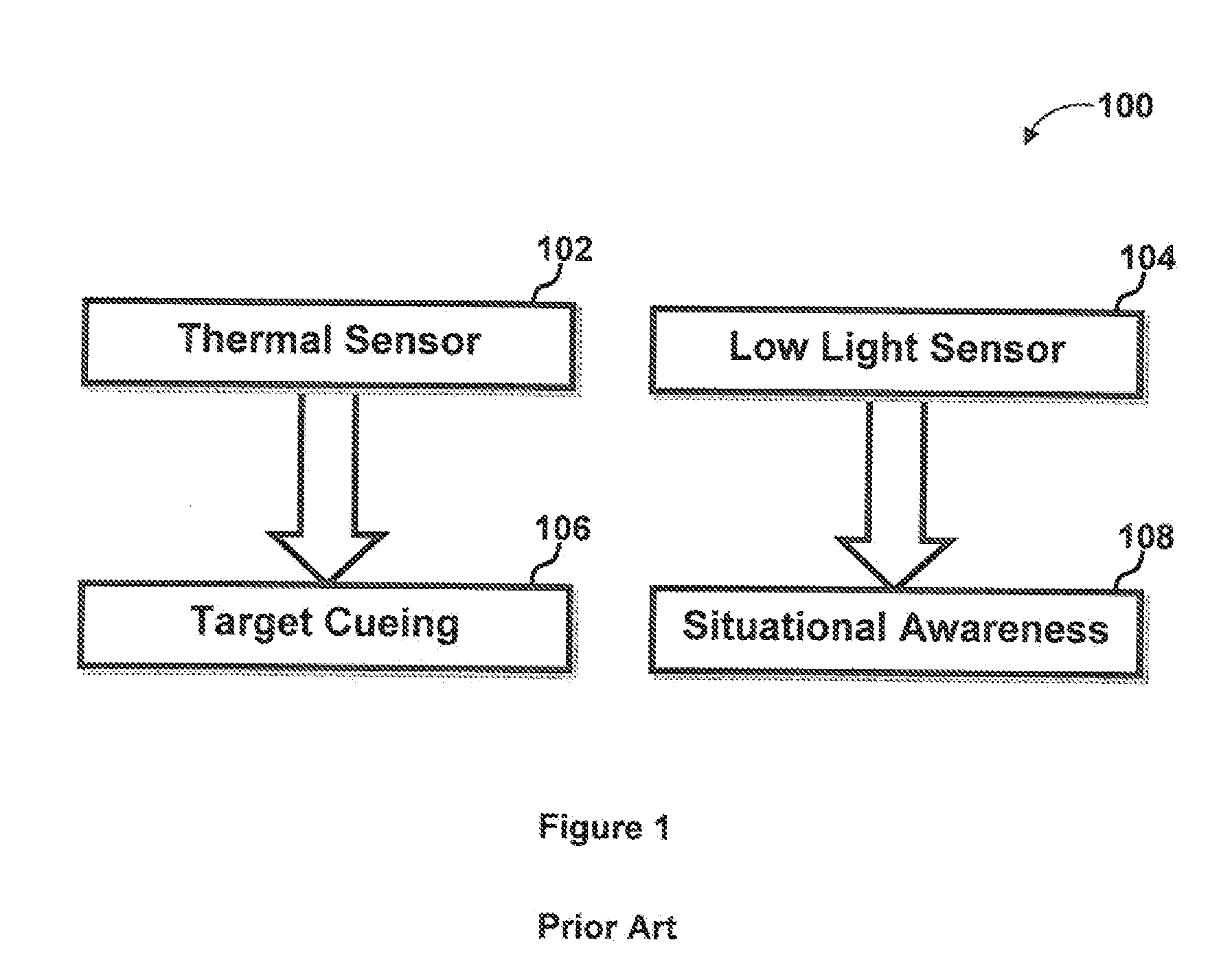
As a result, in extremely low light “dark cave” situations, the LLL sensor 104 cannot provide SA information, as the user is blind to the surroundings.
In case of situational awareness, it is found that resolution tends to deteriorate below overcast starlight.
In dark scenarios, such as low Signal to Noise Ratio (SNR) on low light sensor, the thermal data below the threshold is disgraded and the SA is limited by low level sensor resolution.
None of the existing technologies provides situational awareness for the user in a range of conditions from low light to no light situations.

Method used


Image

  • System and method for situational awareness and target cueing
  • System and method for situational awareness and target cueing
  • System and method for situational awareness and target cueing

Examples


Embodiment Construction

[0026]The particular values and configurations discussed in these non-limiting examples can be varied and are cited merely to illustrate at least one embodiment and are not intended to limit the scope thereof.

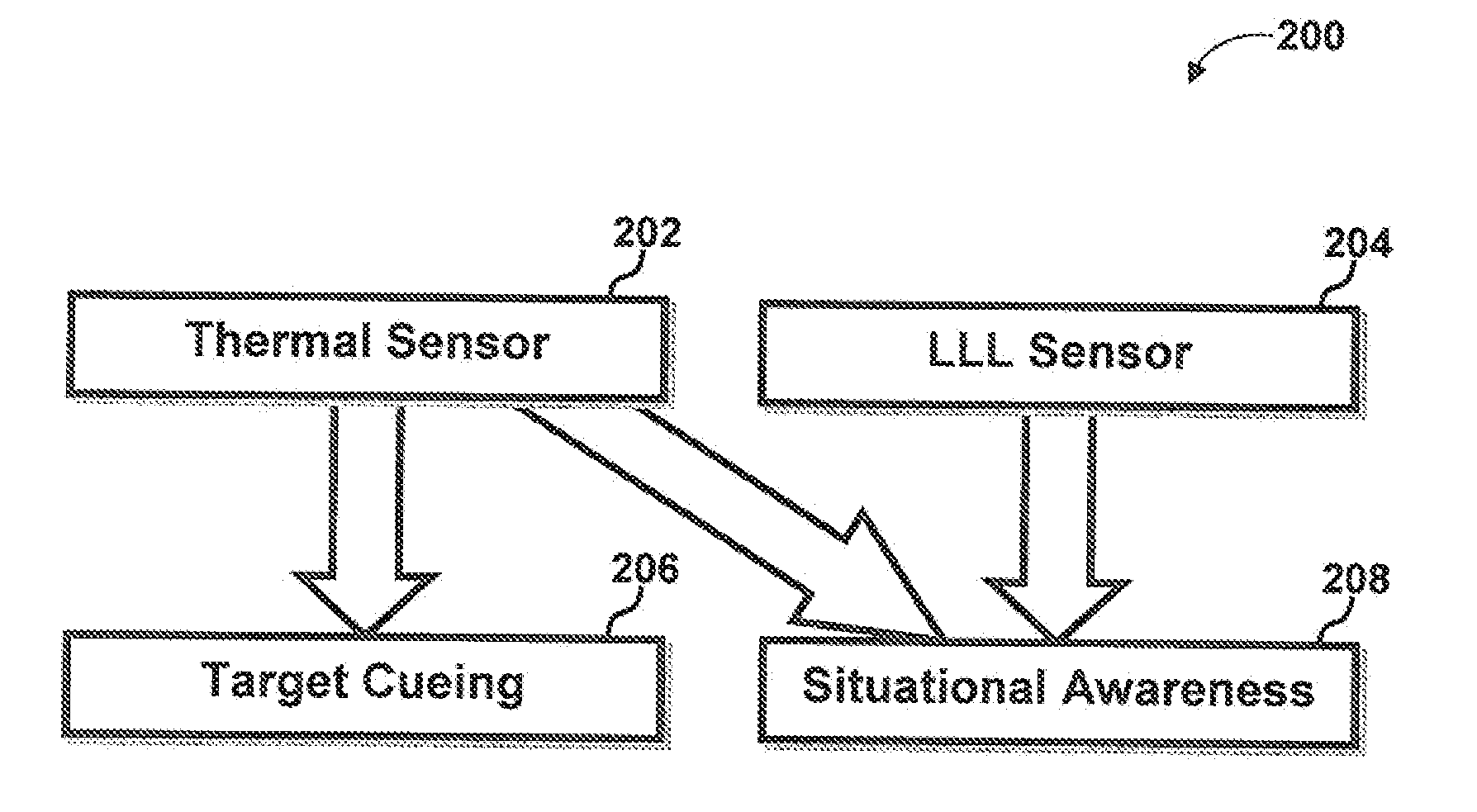
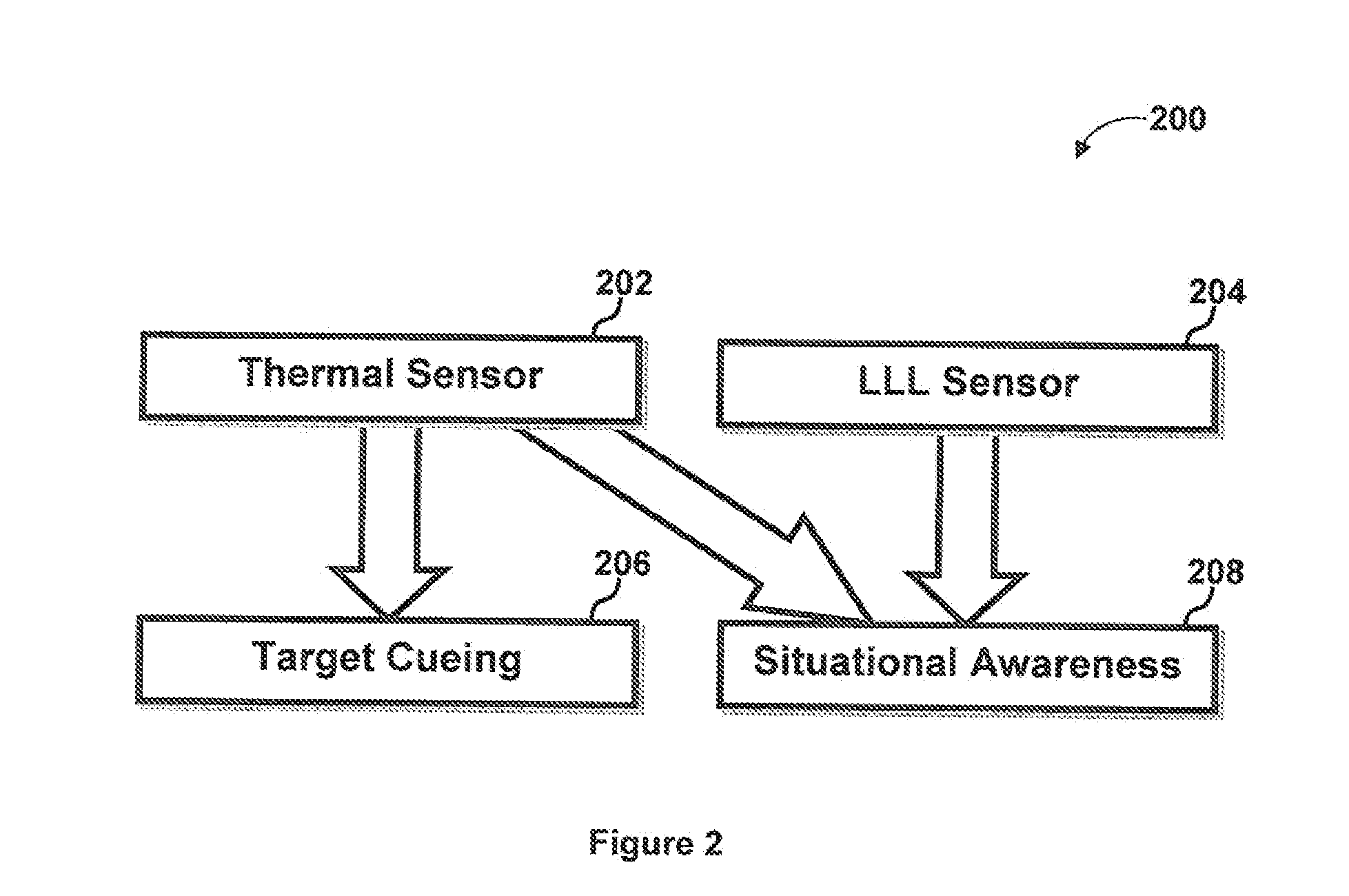
[0027]The present invention provide both situational awareness for mobility and weapon target cueing for thread detection in a range of conditions from low light to no light situations. FIG. 2 illustrates a schematic diagram of a smart fusion night vision system 200 for situational awareness (SA) 208 and target cueing 206. The system 200 bridges the situational awareness 208 performance gap at zero to low light levels. In relatively high light conditions, almost all of the SA 208 is mapped from the Low Light Level (LLL) sensor 204 and target cueing 206 is mapped from thermal sensor 202. As the lighting conditions deteriorate, the Signal to Noise Ratio (SNR) of LLL sensor 204 decreases and hence the contribution of LLL sensor is decreased. In such situations, the system 200 allo...


PUM


Abstract

A system and method for situational awareness and target cueing for use in military applications is disclosed. In extreme low light situations where the LLL sensor cannot provide SA information, the system allocates thermal information to the green SA channel to maintain the supply of contextual information to the user and thus situational awareness (SA) never drops below the native resolution of the thermal sensor. This improved SA capability, surpasses any existing LLL sensor technology in a single channel (stand-alone) application in overcast star light and below conditions.

Description

CROSS-REFERENCE TO RELATED APPLICATIONS[0001]This Application claims rights rider 35 USC §119(e) from U.S. Application Ser. No. 61 / 450,749 filed Mar. 9, 2011, the contents of which are incorporated herein by reference.TECHNICAL FIELD[0002]Embodiments are generally related to night vision systems. Embodiments also relate to situational awareness and target cueing in military applications. Embodiments additionally relate to a system and method to provide situational awareness for mobility and weapon target cueing for thread detection in a range of conditions from low light to no light situations.BACKGROUND OF THE INVENTION[0003]Combat solders, law enforcement personnel, and others exposed to potential dangerous situation, the ready availability of information is essential in all environmental conditions. A Night Vision Device (NVD) is an optical instrument for producing images in levels of light approaching total darkness. NVD usually refers to a complete unit, including an image inte...

Claims


Application Information

Patent Timeline
IPC IPC(8): G06K9/62H04N5/30
CPCG06K9/6289G06K9/3241G06V10/255G06V10/803G06F18/251H04N23/23F41H3/00G02B23/12H04N5/33G01J5/02G08B13/181
Inventor HAYES, HILARY L.KOLTOOKIAN, JOHN H.ROBISON, DEREK T.RENCS, ERIKCHAN, MICHAEL S.
Owner BAE SYST INFORMATION & ELECTRONICS SYST INTERGRATION INC
Learn More