
Use of ruthenium tetroxide as a precursor and reactant for thin film depositions

a technology of ruthenium tetroxide and reactant, which is applied in the direction of coating, chemical vapor deposition coating, metallic material coating process, etc., can solve the problems of inability to allow deposition of films with a sufficient conformality, inability to tolerate the equilibrium between deposition and “etching” if ozone is used, and damage to the sub-layer of the plasma

Active Publication Date: 2013-03-07
AIR LIQUIDE AMERICA INC +1
View PDF10 Cites 264 Cited by
  • Summary
  • Abstract
  • Description
  • Claims
  • Application Information

AI Technical Summary

Benefits of technology

The patent describes a method for depositing films containing ruthenium using atomic layer deposition. The method involves introducing an organometallic precursor and ruthenium tetroxide into a reactor and reacting them to form the ruthenium-containing film. The method can be carried out at various temperatures and pressures, and the ruthenium film can be made using different organometallic precursors such as biscyclopentadienyl ruthenium, tris(acetylacetonate)ruthenium, and tris(octadionato)ruthenium. The method can also be used to deposit ruthenium oxide films using a second organometallic precursor. The rutholutroid precursor can be dissolved in a mixture of non-flammable solvents that contain little moisture. The technical effects of the methods include improved deposition precision, reduced film impurities, and superior film quality.

Problems solved by technology

However, plasma may damage the sub-layers and may not allow deposition of films with a sufficient conformality, especially in deep trenches or holes typically used by memory makers.
Such equilibrium between deposition and “etching” if ozone is used can not be tolerated.

Method used


Image

  • Use of ruthenium tetroxide as a precursor and reactant for thin film depositions
  • Use of ruthenium tetroxide as a precursor and reactant for thin film depositions
  • Use of ruthenium tetroxide as a precursor and reactant for thin film depositions

Examples


##ic example 1

Prophetic Example 1

Deposition of Ruthenium Films Using Ru(EtCp)2 and RuO4

[0091]A solvent blend of RuO4 may be prepared and stored in a canister dipped in a water bath kept at 3° C. to 5° C. Vapors may be introduced into the reactor by pulling vacuum, as the RuO4 vapor pressure is sufficiently high. Ru(EtCp)2 may be stored in a canister heated at 105° C., the temperature at which the molecule is liquid and at which the vapor pressure is sufficiently high. Vapors may be introduced into the reactor by bubbling, the lines being heated to 115° C.

[0092]The reactor may be a cold wall furnace having a volume of 4 L whose walls are heated at 115° C. to avoid condensation of the precursors. The deposition pressure may be set at about 66.7 Pa, for a total of 200 sccm (standard cubic centimeters per minute) of N2 flowing into the furnace.

[0093]Depositions may be performed on silicon and silicon oxide. Vapors of the precursors may be introduced into the reactor separately, separated by N2 purge...

example 2

Deposition of SrRuO3 Films Using Sr(iPr3Cp)2-THF and RuO4

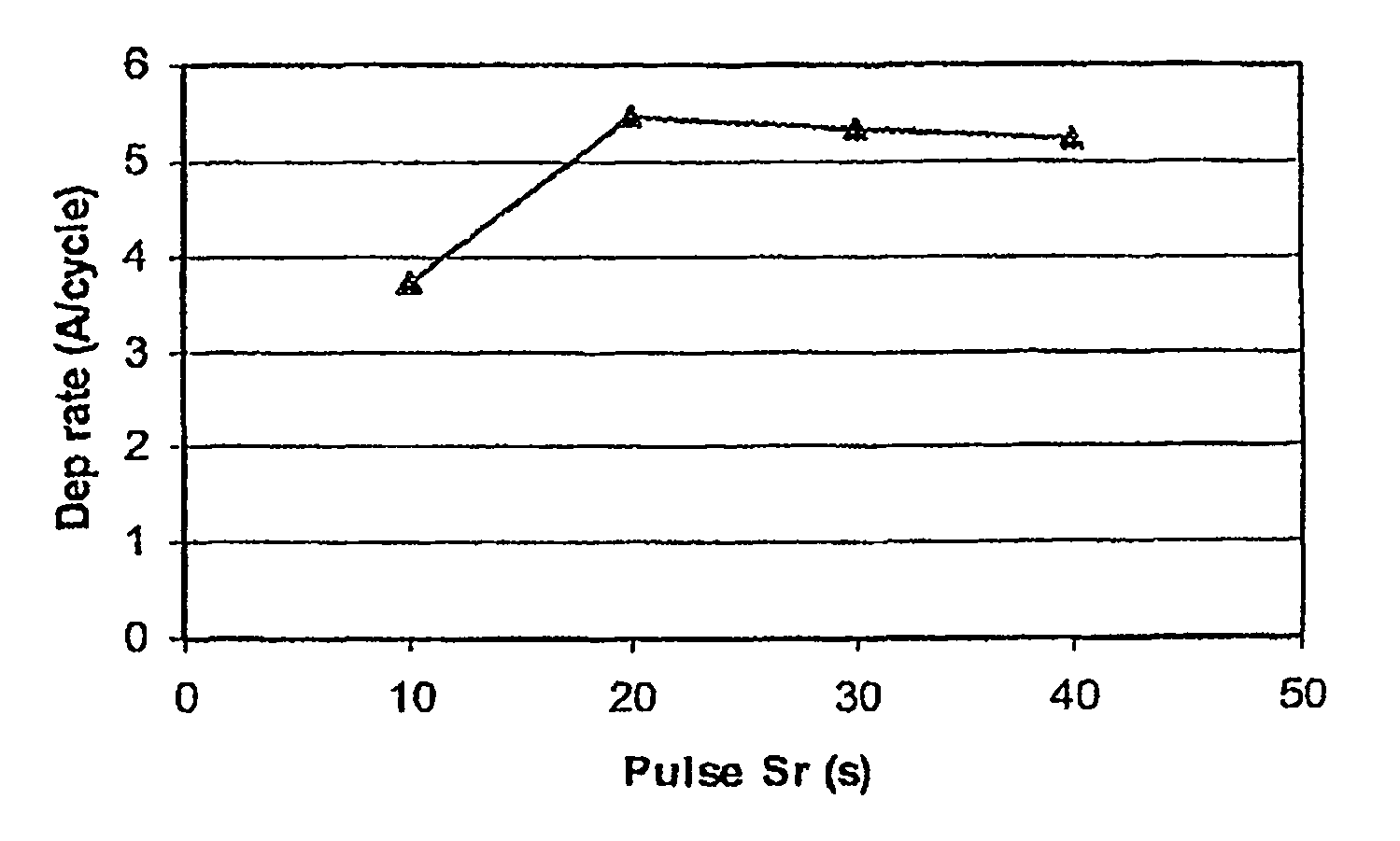
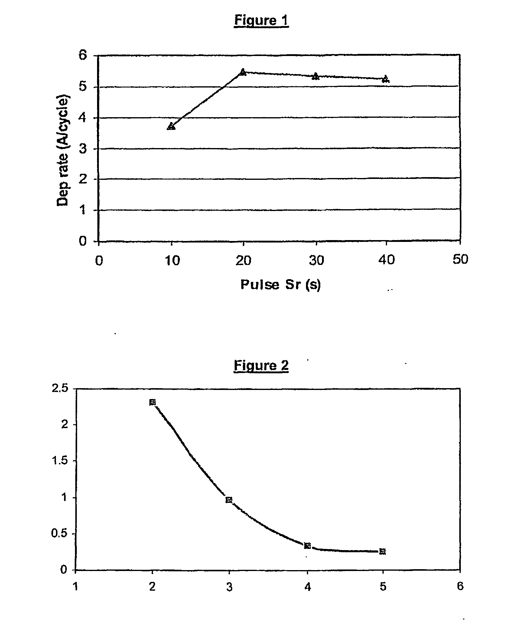
[0096]A solvent blend of RuO4 was prepared and stored in a canister dipped in a water bath kept at a temperature of 3° C. to 5° C. Vapors were introduced into the reactor by pulling vacuum, as the vapor pressure of the RuO4 is sufficiently high. Sr(iPr3Cp)2-THF was stored in a canister heated at 105° C., the temperature at which the molecule is liquid. Vapors were introduced into the reactor by bubbling, the lines being heated at 115° C. Sr(iPr3Cp)2-THF was introduced at a rate of about 0.1 sccm (standard cubic centimeters per minute).

[0097]The reactor is a cold wall furnace having a volume of 4 L whose walls were heated to 115° C. to avoid condensation of the precursors. The deposition pressure was set at 66.7 Pa, for a total of 80 sccm of the carrier gas N2 flowing into the furnace.

[0098]Depositions were performed on silicon, silicon oxide, and ruthenium wafers. Vapors of the precursors were introduced into the reactor sepa...


PUM

PropertyMeasurementUnit
temperatureaaaaaaaaaa

Abstract

Disclosed are atomic layer deposition methods using ruthenium-containing precursors to form ruthenium-containing films for use in the manufacture of semiconductor, photovoltaic, LCD-TFT, or flat panel type devices.

Description

CROSS REFERENCE TO RELATED APPLICATIONS[0001]The present application claims the benefit of U.S. Provisional Application Ser. No. 61 / 307,244 filed Feb. 23, 2010, herein incorporated by reference in its entirety for all purposes.FIELD OF THE INVENTION[0002]Disclosed are atomic layer deposition methods, preferably thermal ALD, using ruthenium-containing precursors to form ruthenium-containing films for use in the manufacture of semiconductor, photovoltaic, LCD-TFT, or flat panel type devices.BACKGROUND[0003]Chemical vapor deposition (CVD) and atomic layer deposition (ALD) have been adopted as techniques for depositing thin films to comply with the scaling down of semiconductor devices. The film growth usually results from the chemical reaction of one or more precursor compounds, so it is essential to develop optimum precursors and understand their reaction process. Sometimes a reactant is introduced to react with the precursor(s), so the choice of an appropriate reactant is also of hig...

Claims


Application Information

Patent Timeline
Patent Type & Authority Applications(United States)
IPC IPC(8): C23C16/18C23C16/40
CPCC23C16/18C23C16/40H01L21/02304H01L21/02197C23C16/45531
Inventor GATINEAU, JULIENDUSSARRAT, CHRISTIAN
Owner AIR LIQUIDE AMERICA INC
Learn More