

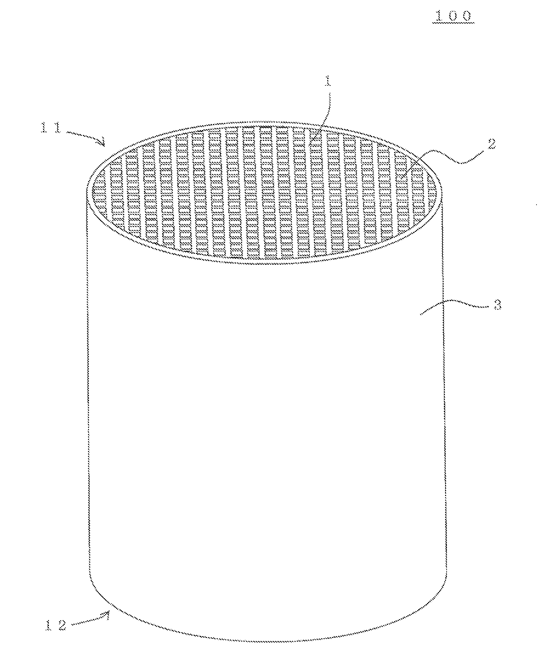
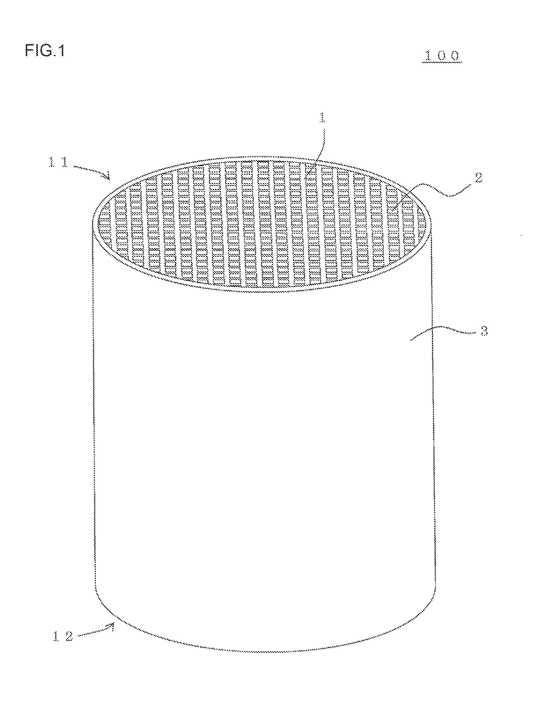
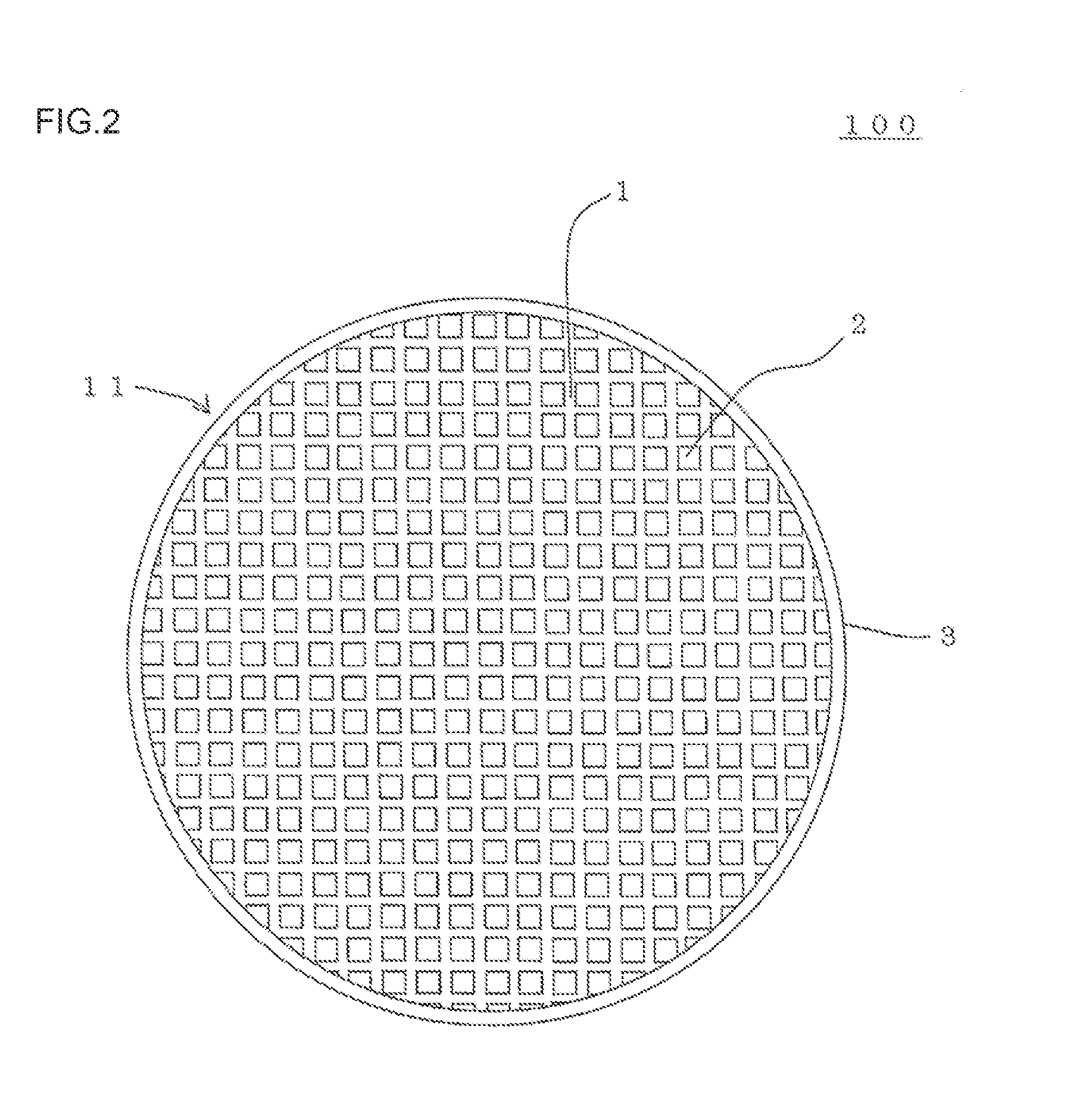
Honeycomb structure and honeycomb catalyst body
a honeycomb and catalyst body technology, applied in physical/chemical process catalysts, metal/metal-oxide/metal-hydroxide catalysts, separation processes, etc., can solve the problems of increasing the pressure loss of the honeycomb catalyst body, increasing the amount of catalyst coating, and affecting the absorption of catalyst water. slurry, water can be easily absorbed by a capillary phenomenon, and the effect of large pores
- Summary
- Abstract
- Description
- Claims
- Application Information
AI Technical Summary
Benefits of technology
Problems solved by technology
Method used
Image

Examples
example 1
[0119]First, a honeycomb structure for use in a honeycomb catalyst body was prepared. As a ceramic raw material to prepare the honeycomb structure, a cordierite forming raw material was used. To the cordierite forming raw material, a pore former, a dispersion medium, an organic binder and a dispersant were added, to prepare a kneaded material for forming. An amount of the dispersion medium to be added was 30 parts by mass to 100 parts by mass of the cordierite forming raw material. An amount of the organic binder to be added was 1 part by mass to 100 parts by mass of the cordierite forming raw material.
[0120]As the cordierite forming raw material, a material including 38.9 parts by mass of talc, 40.7 parts by mass of kaolin and 5.9 parts by mass of alumina was used. An average particle diameter of talc was 3 μm. An average particle diameter of kaolin was 1 μm. An average particle diameter of alumina was 0.3 μm. The above average particle diameter is a median diameter (d50) in a part...
PUM
| Property | Measurement | Unit |
|---|---|---|
| pore diameter distribution | aaaaa | aaaaa |
| porosity | aaaaa | aaaaa |
| porosity | aaaaa | aaaaa |
Abstract
Description
Claims
Application Information