Improvements in backward analysis for determining fault masking factors

a technology of fault masking factor and backward analysis, which is applied in the direction of fault response, error detection/correction, instruments, etc., can solve the problems of systemic faulty behavior, faulty behavior can also be triggered, and the behavior of the user cannot be determined without a lot of effort, so as to achieve the effect of easy determination of the circuit sta

Active Publication Date: 2013-03-07
ROBERT BOSCH GMBH
View PDF4 Cites 32 Cited by
  • Summary
  • Abstract
  • Description
  • Claims
  • Application Information

AI Technical Summary

Benefits of technology

[0060]A combination of the two methods can compensate the weak points of each individual method. In forward simulation, it is difficult or even impossible to take into account transitive masking effects. On the other hand, the circuit state can easily be determined. In backward simulation, the masking effects can easily be determined, but the determination of the circuit state is difficult. If all internal circuit states are now stored for each time step and, in a second simulation run-through, are fed into the circuit from the outside in reversed sequence, the masking effects can be simply and completely determined for the given test pattern set.
[0061]The example method can be applied to all types of storage devices and digital circuits; flip-flops, latches, SRAM b...

Problems solved by technology

Electronic circuits, in particular digital circuits having for example semiconductor components, are exposed to external influences that can cause undesired changes in their behavior.
If one or more parameters are outside these limits, systematic faulty behavior may be observed.
However, faulty behavior can also be triggered by other external influences, such as electromagnetic radiation or high-energy particles such as cosmic radiation, radioactive decay products, etc.
If a transient fault occurs in one or more input signals to a logic function with an output (1 bit), a faulty output signal may occur, as a function of the input signals and the logic function.
The determination of a masking factor through fault injection requires a very high computing expense, because in a simulation it is always possible to draw only one conclusion for a specific fault.
In addition to faults that occur during circuit operation, manufacturing faults in the circuits must also be recognized.
However, in the production of these test patterns it is often not yet known which faults are recognized using the test pattern set.
Because many fault lists on non-sensitive paths are erased, a large unnecessary computing expense is incurred.
However, the unification of all these results yields faults, because the results are not completely independent of one another.
In addition, complex masking effects such as FDD and TDD cannot be taken into account, or can be taken into account only with difficulty.
Conventional...

Method used


Image

  • Improvements in backward analysis for determining fault masking factors
  • Improvements in backward analysis for determining fault masking factors
  • Improvements in backward analysis for determining fault masking factors

Examples


Embodiment Construction

[0070]The present invention is schematically shown in the drawings on the basis of specific embodiments, and is described in detail with reference to the drawings.

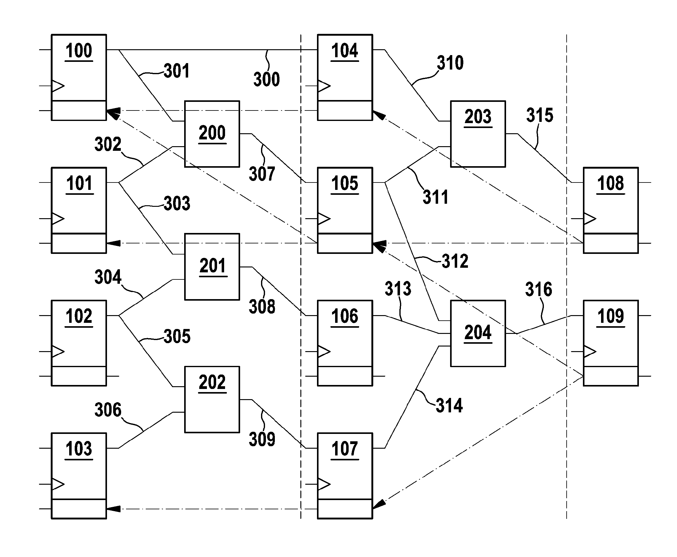
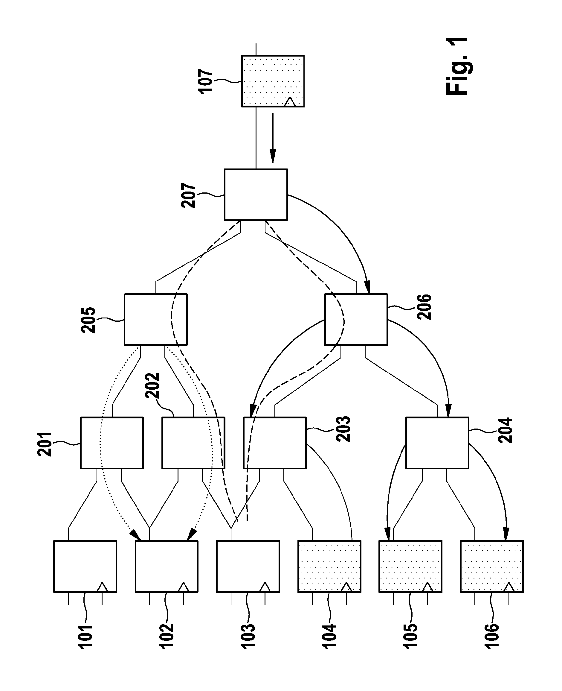
[0071]FIG. 1 shows a sensitive path from an input to an output, in which a change of the input signal causes a change in the output signal.

[0072]The figure schematically shows how sensitive paths go out from a register, as an example of a storage element. It is assumed that the occupation of registers 101 through 106 by the output signals is such as to bring about the sensitive paths (solid arrows) assumed below. The function of logic blocks 201 through 207 is not specified in more detail.

[0073]Going out from register 107, there result sensitive paths via logic gates 207, 206, 203 to register 104, and via 207, 206, 204 to registers 105 and 106. There is no sensitive path to register 101. Registers 102 and 103 are situated in particular structures. Both registers are the beginning of a reconvergent path. Two possible situat...


PUM


Abstract

A method and a system are presented for determining the observability of faults in an electronic circuit. In the method, for each element the time periods are determined in which an occurrent fault could cause a deviation in analysis output signals.

Description

FIELD OF THE INVENTION[0001]The present invention relates to a method for determining the observability of faults in an electronic circuit, and a system for carrying out the method.BACKGROUND INFORMATION[0002]Electronic circuits, in particular digital circuits having for example semiconductor components, are exposed to external influences that can cause undesired changes in their behavior. A correct, fault-free behavior of the circuit can be expected by the user when all operating parameters, such as operating voltage, temperature, mechanical load, etc., are within the specified limits. If one or more parameters are outside these limits, systematic faulty behavior may be observed.[0003]However, faulty behavior can also be triggered by other external influences, such as electromagnetic radiation or high-energy particles such as cosmic radiation, radioactive decay products, etc. The frequency of occurrence of such radiation influence is a function in particular of the location at whic...

Claims


Application Information

Patent Timeline
IPC IPC(8): G01R31/28G06F11/07
CPCG01R31/318357G01R31/3183G01R31/31835G06F30/00
Inventor HARTL, ROBERT
Owner ROBERT BOSCH GMBH
Why Eureka
Try Eureka