
Motor and washing machine having the same

a technology of washing machine and motor, applied in the field of motors, can solve the problems of material cost and motor miniaturization disadvantages, and achieve the effect of reducing the leakage of magnetic flux

Active Publication Date: 2013-03-14
SAMSUNG ELECTRONICS CO LTD
View PDF6 Cites 13 Cited by
  • Summary
  • Abstract
  • Description
  • Claims
  • Application Information

AI Technical Summary

Benefits of technology

The present disclosure describes an improved motor structure that reduces magnetic flux leakage and demagnetization of magnets. The motor includes a rotor with a plurality of magnets and a stator with stator cores and coils. The rotor cores are alternated with the magnets to concentrate magnetic flux on the rotor cores. The motor also includes a molded body to support the magnets and a separation preventing hole to prevent the rotor from separating due to centrifugal force. The motor also includes demagnetization preventers that regulate the spacing between the magnets and stator cores or neighboring rotor cores to prevent magnetic flux from reaching the magnets and influencing magnetic flux formed at the magnets. The patent also describes the use of a magnet design that increases the length of the magnetic flux leakage path to further reduce magnetic flux leakage. The motor with the improved structure can be used in various applications such as washing machines.

Problems solved by technology

In this case, accordingly, there may be disadvantages in terms of material cost and motor miniaturization.

Method used


Image

  • Motor and washing machine having the same
  • Motor and washing machine having the same
  • Motor and washing machine having the same

Examples


Embodiment Construction

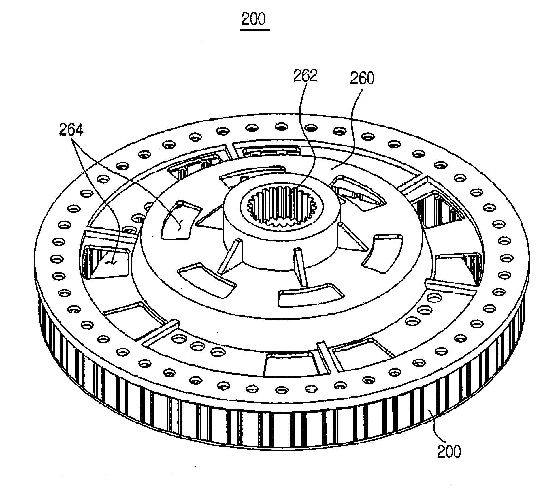
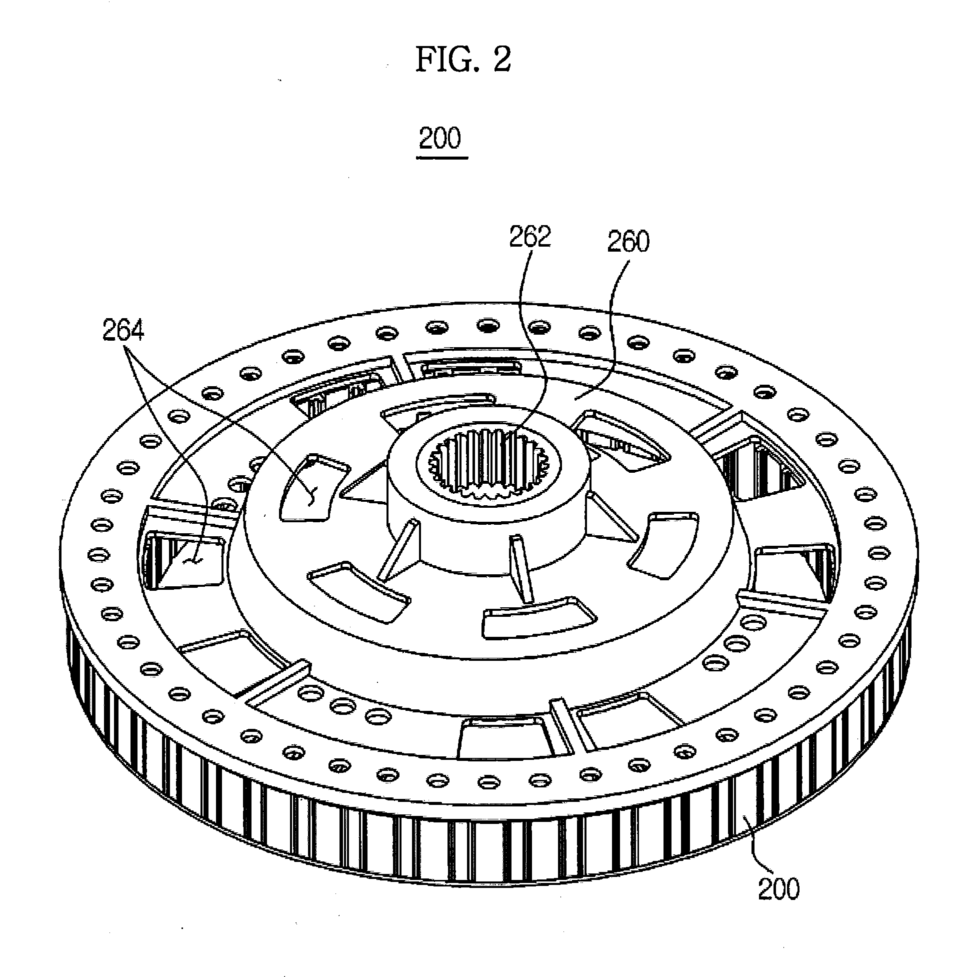
[0046]Hereinafter, embodiments of the present disclosure will be described with reference to the accompanying drawings. Motors according to respective embodiments of the present disclosure may be applied to various appliances such as a washing machine, an air conditioner, an electric vehicle, a light rail transit train, an electric bicycle, a small electric generator, each of which uses a motor as a power source.

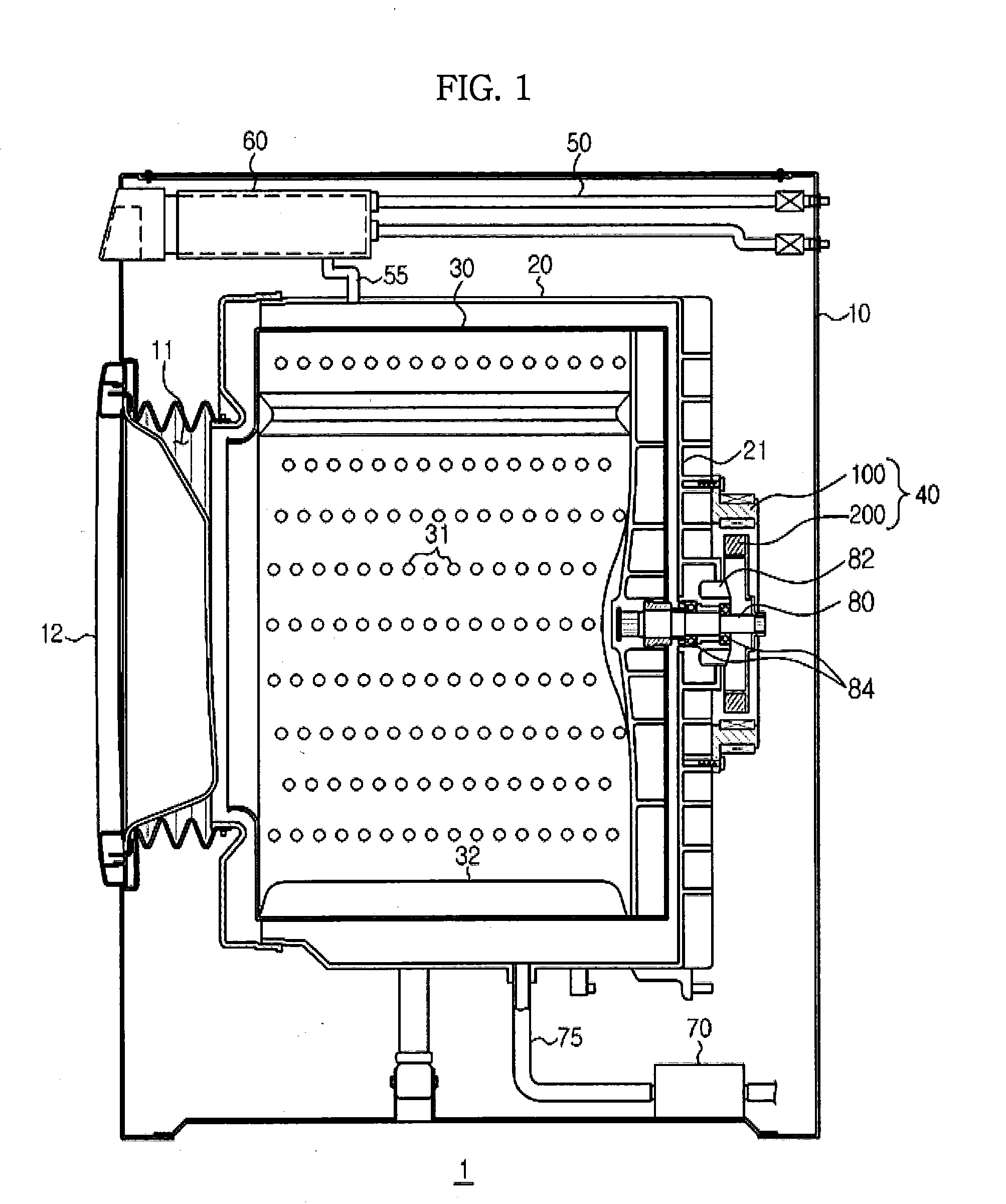
[0047]FIG. 1 is a washing machine according to an exemplary embodiment of the present disclosure.

[0048]As shown in FIG. 1, the washing machine, which is designated by reference numeral “1”, includes a cabinet 10 to form an outer appearance of the washing machine, a tub 20 disposed within the cabinet 10, a drum 30 rotatably disposed within the tub 20, and a motor 40 to drive the drum 30.

[0049]A loading opening 11 is formed at a front wall of the cabinet 10, to allow loading of laundry into the drum 30. The loading opening 11 is opened or closed by a door 12 installed at the f...


PUM

PropertyMeasurementUnit
Lengthaaaaaaaaaa
Lengthaaaaaaaaaa
Angleaaaaaaaaaa

Abstract

A motor having a structure capable of achieving a reduction in magnetic flux leakage occurring at a rotor and a washing machine, to which the motor is applied. The motor includes a stator including a plurality of stator cores arranged in a circumferential direction, and coils respectively wound around the stator cores, and a rotor rotatably arranged inside the stator. The rotor includes a plurality of rotor cores arranged in a circumferential direction of the rotor, a plurality of magnets each disposed between neighboring ones of the rotor cores such that the magnet extends in an axial direction of the rotor outwardly of upper and lower surfaces of the neighboring rotor cores, and a molded body to support the plurality of rotor cores and the plurality of magnets. The molding body includes a shaft hole, to which a motor shaft is coupled.

Description

CROSS-REFERENCE TO RELATED APPLICATIONS[0001]This application claims the benefit of Korean Patent Application No. 10-2011-91003, filed on Sep. 8, 2011 in the Korean Intellectual Property Office, the disclosure of which is incorporated herein by reference.BACKGROUND[0002]1. Field[0003]Embodiments of the present disclosure relate to a motor having an improved structure capable of achieving a reduction in magnetic flux leakage.[0004]2. Description of the Related Art[0005]A motor is a machine to produce rotating force from electrical energy. Such a motor includes a stator and a rotor. The rotor is configured to co-operate with the stator in an electromagnetic manner. The rotor is rotated by a force exerted between a magnetic filed and current flowing through a coil.[0006]Permanent magnet motors, which use permanent magnets to generate an electric field, may be classified into a surface mounted permanent magnet motor, an interior type permanent magnet motor, and a spoke type permanent ma...

Claims


Application Information

Patent Timeline
IPC IPC(8): D06F23/00H02K1/22H02K15/00H02K1/30
CPCH02K1/148H02K1/2773Y10T29/49009H02K15/10H02K1/30H02K1/27
Inventor YOON, KEUN YOUNGKIM, YOUNG KWANLEE, SUNG GU
Owner SAMSUNG ELECTRONICS CO LTD
Learn More