Thermagnonic spin-torque oscillator(STO) and sensor utilizing same to detect shifts in the free layer magnetization oscillation frequency

a spin-torque oscillator and spin-torque technology, applied in the field of spin-torque oscillator, can solve the problems of large sto power and large siz

Active Publication Date: 2013-03-14
WESTERN DIGITAL TECH INC
View PDF0 Cites 10 Cited by
  • Summary
  • Abstract
  • Description
  • Claims
  • Application Information

AI Technical Summary

Benefits of technology

[0007]The STO according to the present invention is a “thermagnonic” STO that uses heat flow alone to cause the ST effect and generate the persistent oscillation of the free layer magnetization. The thermagnonic STO can also function as an STO magnetic field sensor, such as a magnetic recording disk drive read head. In addition to the conventional free and reference layers, the thermagnonic STO also includes a magnetic oxide layer having a fixed in-plane magnetization, a ferromagnetic metallic layer on one surface of the magnetic oxide layer, a nonmagnetic electrically conductive layer between the free layer and the metallic layer, and an electrically resistive heater on the other surface of the magnetic oxide layer. Due to the thermagnonic effect, heat flow from the magnetic oxide layer through the metallic layer, conductive layer and free layer ultimately results in a spin transfer torque (STT) to the free layer. Electrical sense current flowing in the opposite direction as the heat flow is used to monitor the frequency of oscillation of the free layer magnetization. Because the sense current electron flow is in the same direction as the heat flow, the electron current does not exert appreciable spin-torque on the free layer. In this way the flow of heat provides a means of generating ST on the free layer that is independent of the charge current flow used to sense the oscillation. This allows for a large charge current to be applied which results in large STO power, much larger than if the spin current associated with charge current flow alone were used to generate oscillations.

Problems solved by technology

This allows for a large charge current to be applied which results in large STO power, much larger than if the spin current associated with charge current flow alone were used to generate oscillations.

Method used


Image

  • Thermagnonic spin-torque oscillator(STO) and sensor utilizing same to detect shifts in the free layer magnetization oscillation frequency
  • Thermagnonic spin-torque oscillator(STO) and sensor utilizing same to detect shifts in the free layer magnetization oscillation frequency
  • Thermagnonic spin-torque oscillator(STO) and sensor utilizing same to detect shifts in the free layer magnetization oscillation frequency

Examples


Embodiment Construction

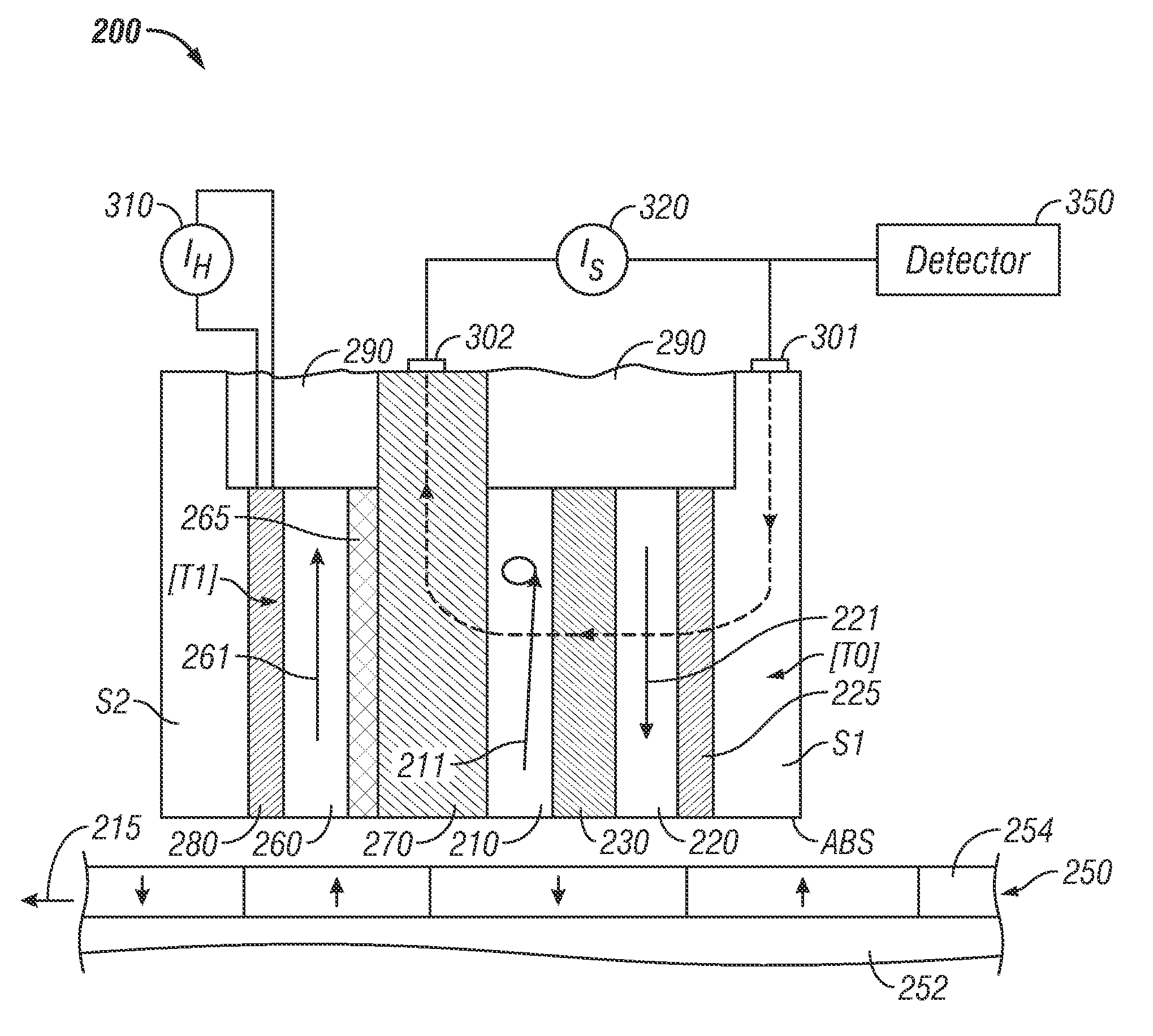
[0015]The STO according to the invention has applications other than as a magnetic field sensor, but will be described in detail below as magnetic recording disk drive read head.

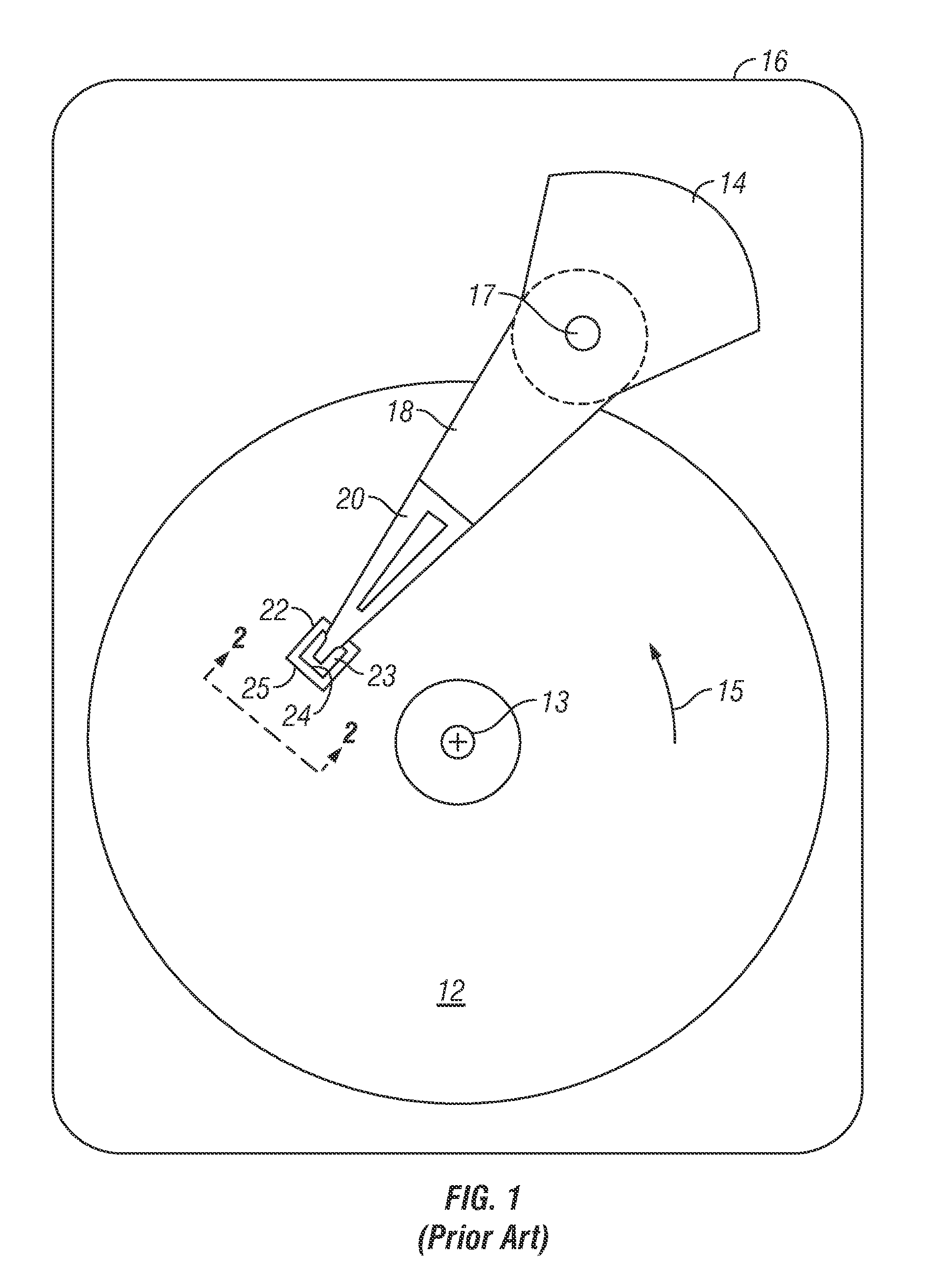
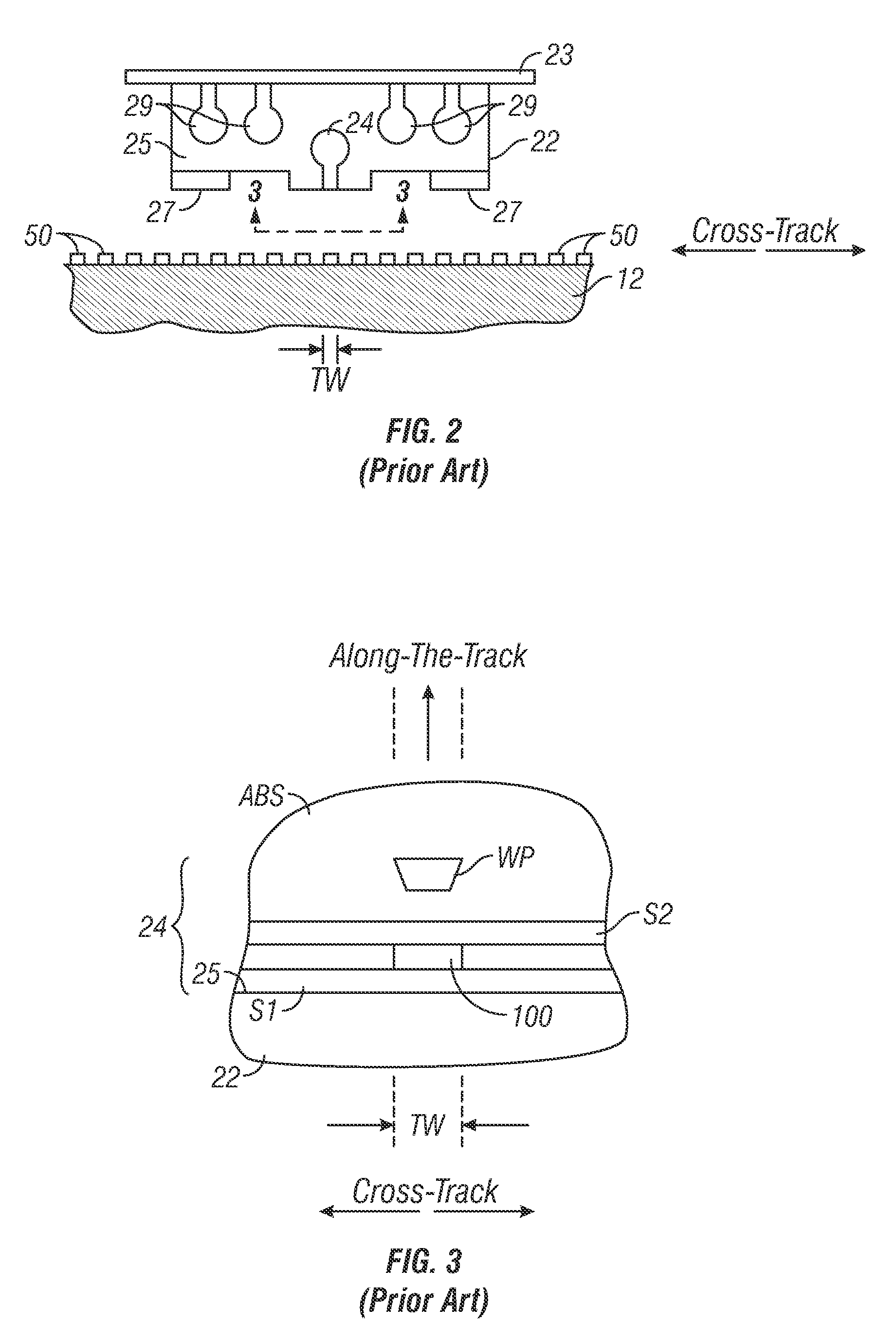
[0016]FIGS. 1-4 illustrate a conventional CPP magnetoresistive (MR) magnetic field sensing sensor and system. FIG. 1 is a block diagram of a conventional magnetic recording hard disk drive. The disk drive includes a magnetic recording disk 12 and a rotary voice coil motor (VCM) actuator 14 supported on a disk drive housing or base 16. The disk 12 has a center of rotation 13 and is rotated in direction 15 by a spindle motor (not shown) mounted to base 16. The actuator 14 pivots about axis 17 and includes a rigid actuator arm 18. A generally flexible suspension 20 includes a flexure element 23 and is attached to the end of arm 18. A head carrier or air-bearing slider 22 is attached to the flexure 23. A magnetic recording read / write head 24 is formed on the trailing surface 25 of slider 22. The flexure 23 and s...


PUM

PropertyMeasurementUnit
thicknessaaaaaaaaaa
thicknessaaaaaaaaaa
thicknessaaaaaaaaaa

Abstract

A “thermagnonic” spin-torque oscillator (STO) uses heat flow alone to cause the spin-torque (ST) effect and generate the persistent oscillation of the free layer magnetization. In addition to the conventional free and reference layers, the thermagnonic STO also includes a magnetic oxide layer having a fixed in-plane magnetization, a ferromagnetic metallic layer on one surface of the magnetic oxide layer, a nonmagnetic electrically conductive layer between the free layer and the metallic layer, and an electrically resistive heater on the other surface of the magnetic oxide layer. Due to the thermagnonic effect, heat flow from the magnetic oxide layer through the metallic layer, conductive layer and free layer ultimately results in a spin transfer torque (STT) to the free layer. Electrical sense current flowing in the opposite direction as the heat flow is used to monitor the frequency of oscillation of the free layer magnetization.

Description

FIELD OF THE INVENTION[0001]The invention relates generally to a spin-torque oscillator (STO), and more particularly to a magnetic field sensor and sensing system that uses a STO sensor.BACKGROUND OF THE INVENTION[0002]One type of conventional magnetoresistive (MR) sensor used as the read head in magnetic recording disk drives is a “spin-valve” sensor based on the giant magnetoresistance (GMR) effect. A GMR spin-valve sensor has a stack of layers that includes two ferromagnetic layers separated by a nonmagnetic electrically conductive spacer layer, which is typically copper (Cu). One ferromagnetic layer adjacent the spacer layer has its magnetization direction fixed, such as by being pinned by exchange coupling with an adjacent antiferromagnetic layer, and is referred to as the reference layer. The other ferromagnetic layer adjacent the spacer layer has its magnetization direction free to rotate in the presence of an external magnetic field and is referred to as the free layer. With...

Claims


Application Information

Patent Timeline
Patent Type & Authority Applications(United States)
IPC IPC(8): H01L29/82G11B5/48
CPCG11B5/3903G11B2005/0002G01R33/1284G01R33/098G01R33/093
Inventor BRAGANCA, PATRICK MESQUITAGURNEY, BRUCE ALVIN
Owner WESTERN DIGITAL TECH INC
Why Eureka
Try Eureka