Method and device to synthesize boron nitride nanotubes and related nanoparticles

a boron nitride nanotube and nanoparticle technology, applied in the field of chemical nanostructures, can solve the problems of not being easily scaled up to meaningful industrial production levels, and bnnts and related materials have not enjoyed widespread application

Active Publication Date: 2013-03-14
RGT UNIV OF CALIFORNIA
View PDF4 Cites 71 Cited by
  • Summary
  • Abstract
  • Description
  • Claims
  • Application Information

AI Technical Summary

Benefits of technology

[0016]The present invention relates to improved methods and devices for the production of BxCyNz nanotubes and related particles, such as described in the above-referenced U.S. Pat. No. 6,231,980. The device is generally applicable to any nanomaterial where different elements are to be combined under controlled conditions of stoichiometry, temperature, concentration and pressure.

Problems solved by technology

Unfortunately, all of these methods are not easily scaled up to meaningful industrial production levels.
The synthesis bottleneck is the major reason BNNTs and related materials have not enjoyed widespread application.

Method used


Image

  • Method and device to synthesize boron nitride nanotubes and related nanoparticles
  • Method and device to synthesize boron nitride nanotubes and related nanoparticles
  • Method and device to synthesize boron nitride nanotubes and related nanoparticles

Examples


specific embodiments

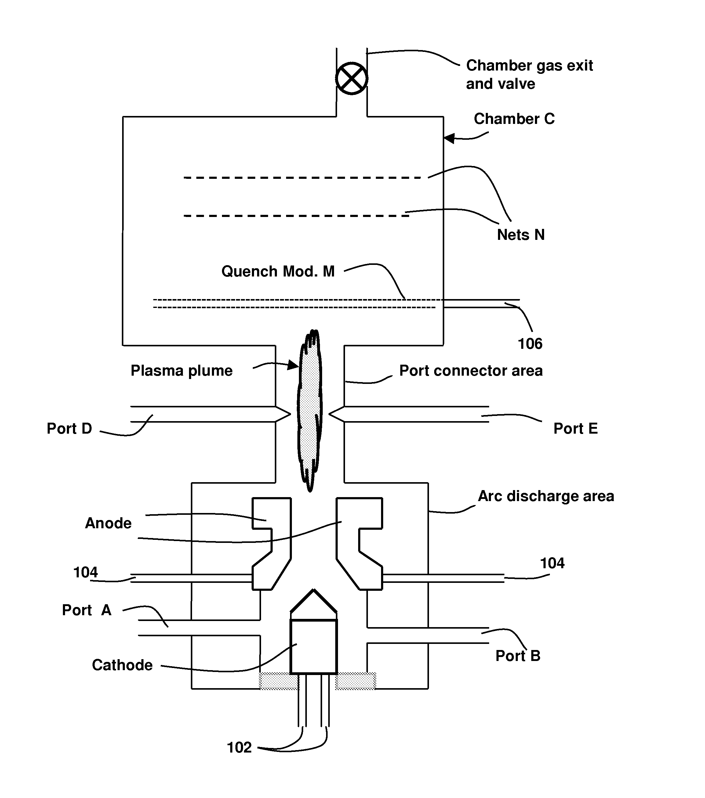
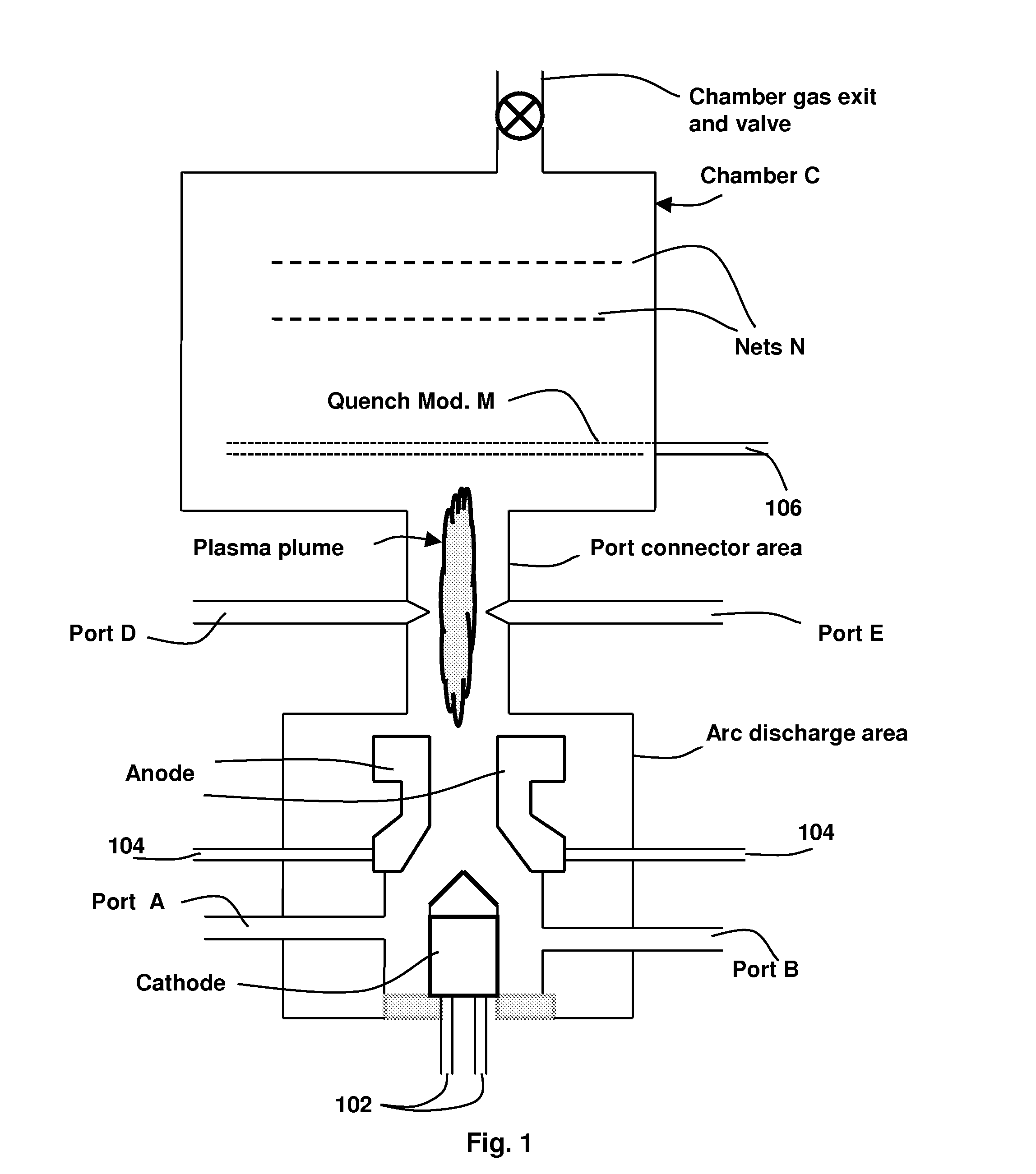
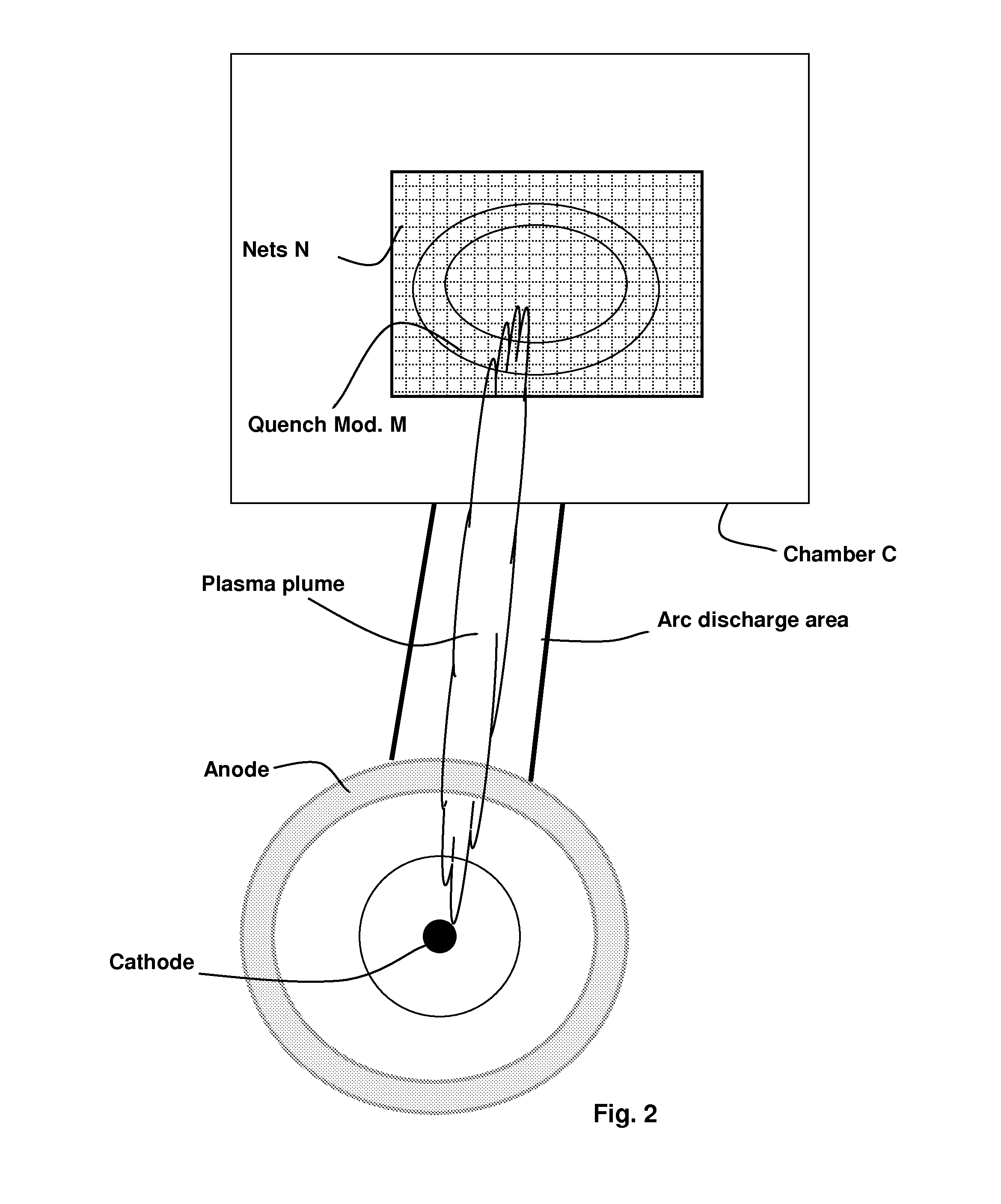
[0031]Referring now to FIGS. 1 and 2, the present structure may be viewed as having three modules: an arc discharge area for creating a plasma plume or jet, shown towards the bottom of FI. 1 and in the middle of FIG. 2; a port connector area, receiving plasma from the arc discharge area, for modulating and directing the plasma plume; and an environmental chamber C, connected to the port connector area downstream of the port connector, for collecting feed materials formed into the nanomaterials in a controlled environment. As shown in FIG. 1, the arc discharge area is on the bottom, and the port connector and environmental chamber are arranged in turn directly above; this takes in to account the tendency of hot gases to rise; other arrangements are possible. The arc discharge area, in which a plasma is formed, comprises an inlet(s) for a gaseous stream (e.g., ports A and / or B). The gaseous stream flows through a nozzle-like anode and cathode arrangement as shown. The anode and cathod...


PUM

PropertyMeasurementUnit
lengthaaaaaaaaaa
pressureaaaaaaaaaa
diameteraaaaaaaaaa

Abstract

Methods and apparatus for producing chemical nanostructures having multiple elements, such as boron and nitride, e.g. boron nitride nanotubes, are disclosed. The method comprises creating a plasma jet, or plume, such as by an arc discharge. The plasma plume is elongated and has a temperature gradient along its length. It extends along its length into a port connector area having ports for introduction of feed materials. The feed materials include the multiple elements, which are introduced separately as fluids or powders at multiple ports along the length of the plasma plume, said ports entering the plasma plume at different temperatures. The method further comprises modifying a temperature at a distal portion of or immediately downstream of said plasma plume; and collecting said chemical nanostructures after said modifying.

Description

CROSS-REFERENCE TO RELATED APPLICATIONS[0001]This application claims priority from U.S. Provisional Patent Application No. 61 / 316,101, filed on Mar. 22, 2010, which is hereby incorporated by reference in its entirety.STATEMENT OF GOVERNMENTAL SUPPORT[0002]This invention was made with U.S. Government support under Contract Number DE-AC02-05CH11231 between the U.S. Department of Energy and The Regents of the University of California for the management and operation of the Lawrence Berkeley National Laboratory. The U.S. Government has certain rights in this invention.REFERENCE TO SEQUENCE LISTING, COMPUTER PROGRAM, OR COMPACT DISK[0003]None.BACKGROUND OF THE INVENTION[0004]1. Field of the Invention[0005]The present invention relates to chemical nanostructures having multiple elements, such as nanotubes and nanoparticles, more specifically to nanotubes and nanoparticles containing the elements of boron, carbon and nitrogen, and more specifically to synthesis of such materials using a pl...

Claims


Application Information

Patent Timeline
Patent Type & Authority Applications(United States)
IPC IPC(8): C01B21/064B01J19/00B01J19/26B82Y30/00B82Y40/00
CPCD01F9/08C04B35/6229Y10S977/831Y10S977/896B01J19/088B01J2219/0809B01J2219/0824B01J2219/0898B82Y40/00C01B21/0641
Inventor ZETTL, ALEXANDER K.
Owner RGT UNIV OF CALIFORNIA
Why Eureka
Try Eureka