Waste heat recovery system

a heat recovery system and waste heat technology, applied in indirect heat exchangers, machines/engines, light and heating apparatus, etc., can solve the problems of reducing the recovery of energy in the rankine cycle device, difficulty in sufficiently cooling the intake fluid, and excessive cooling of the working fluid

Inactive Publication Date: 2013-03-21
TOYOTA IND CORP
View PDF0 Cites 41 Cited by
  • Summary
  • Abstract
  • Description
  • Claims
  • Application Information

AI Technical Summary

Problems solved by technology

In the above-described waste heat recovery systems, however, it is difficult to sufficiently cool the intake fluid such as compressed air or recirculation exhaust gas because the condenser is connected directly to the pump and hence the temperature of the working fluid entering the compressed air boiler or of the working fluid entering the exhaust gas boiler is approximate to the condensation temperature.
In such case, however, only a given amount of heat is released from the condenser and the subcooler regardless of the output of the engine, with the result that the working fluid may be cooled excessively and the recovery of energy in the Rankine cycle device may be reduced.
When compressed air or recirculation exhaust gas need to be cooled further in order to increase engine output, in other words, when the required cooling load for the compressed air or the recirculation exhaust gas is high, the compressed air and the recirculation exhaust gas cannot be cooled to the desired temperature level, which may results in reduced performance of the engine.

Method used


Image

  • Waste heat recovery system
  • Waste heat recovery system
  • Waste heat recovery system

Examples


first embodiment

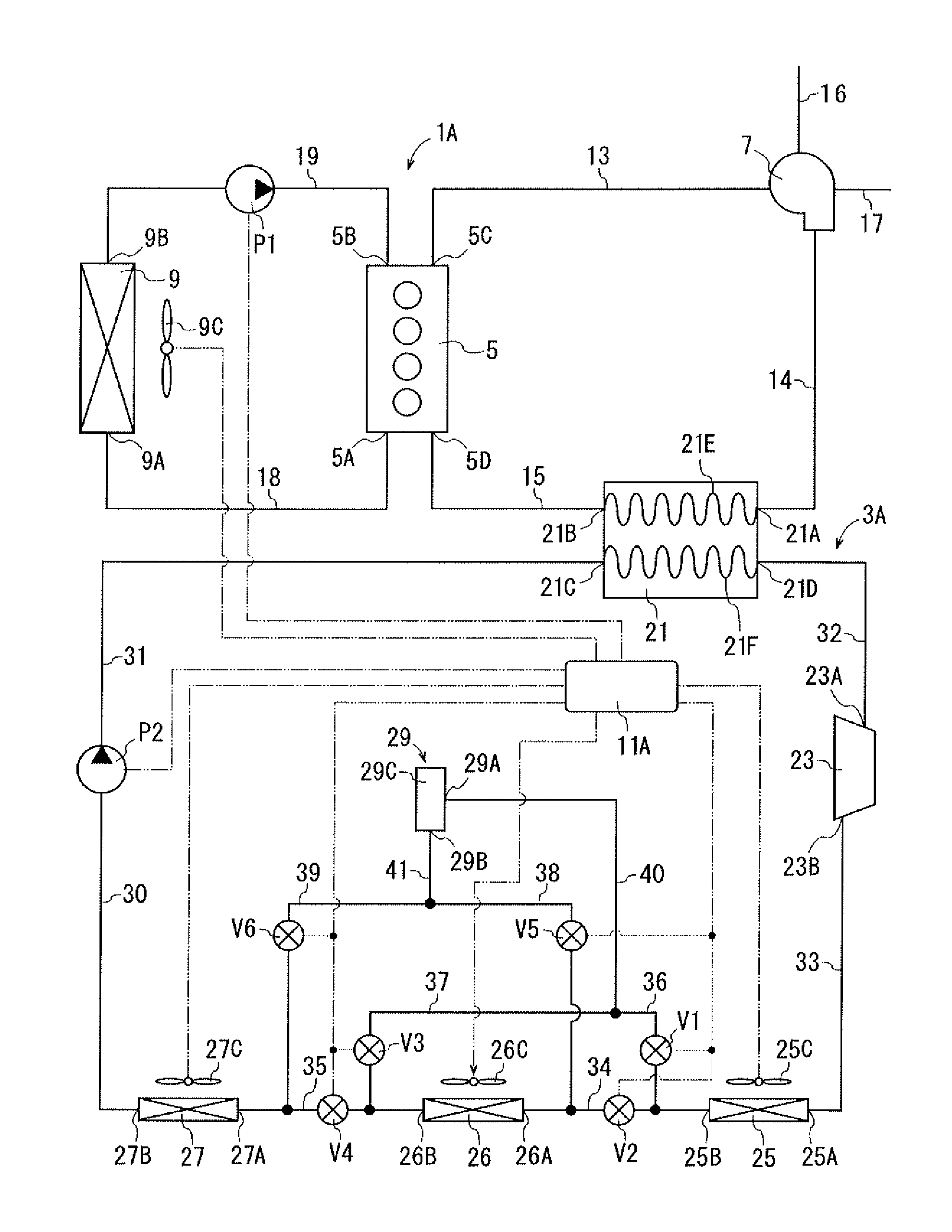
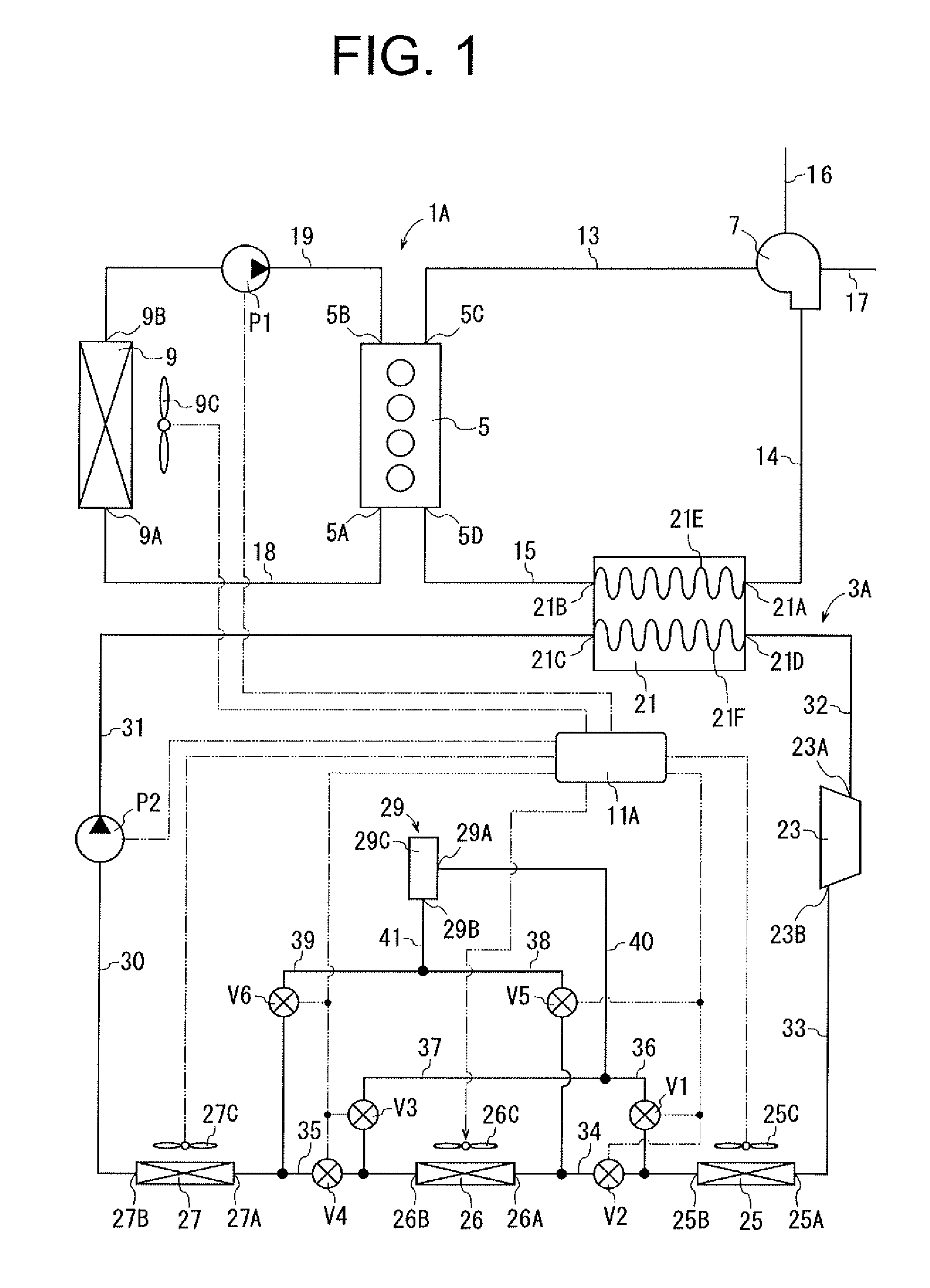
[0027]Referring to FIG. 1, the waste heat recovery system of the first embodiment is installed in a vehicle and used with a power unit 1A of the vehicle. The waste heat recovery system includes a Rankine cycle device 3A and a controller 11A. The controller 11A corresponds to the determination device of the present invention.

[0028]The power unit 1A has an internal combustion engine 5, a turbocharger 7 as a forced-induction compressor, and a radiator 9. The engine 5 is a conventional water-cooled gasoline engine having a water jacket (not shown) through which coolant flows. The engine 5 has an inlet 5B and an outlet 5A through which coolant flows into and out of the water jacket. The engine 5 further has an outlet 5C for discharging exhaust gas and an inlet 5D for introducing compressed air.

[0029]The turbocharger 7 and the radiator 9 are of a widely used type. The turbocharger 7 is driven by the exhaust gas exiting the engine 5 to compress the intake air. Compressed air is supplied as...

second embodiment

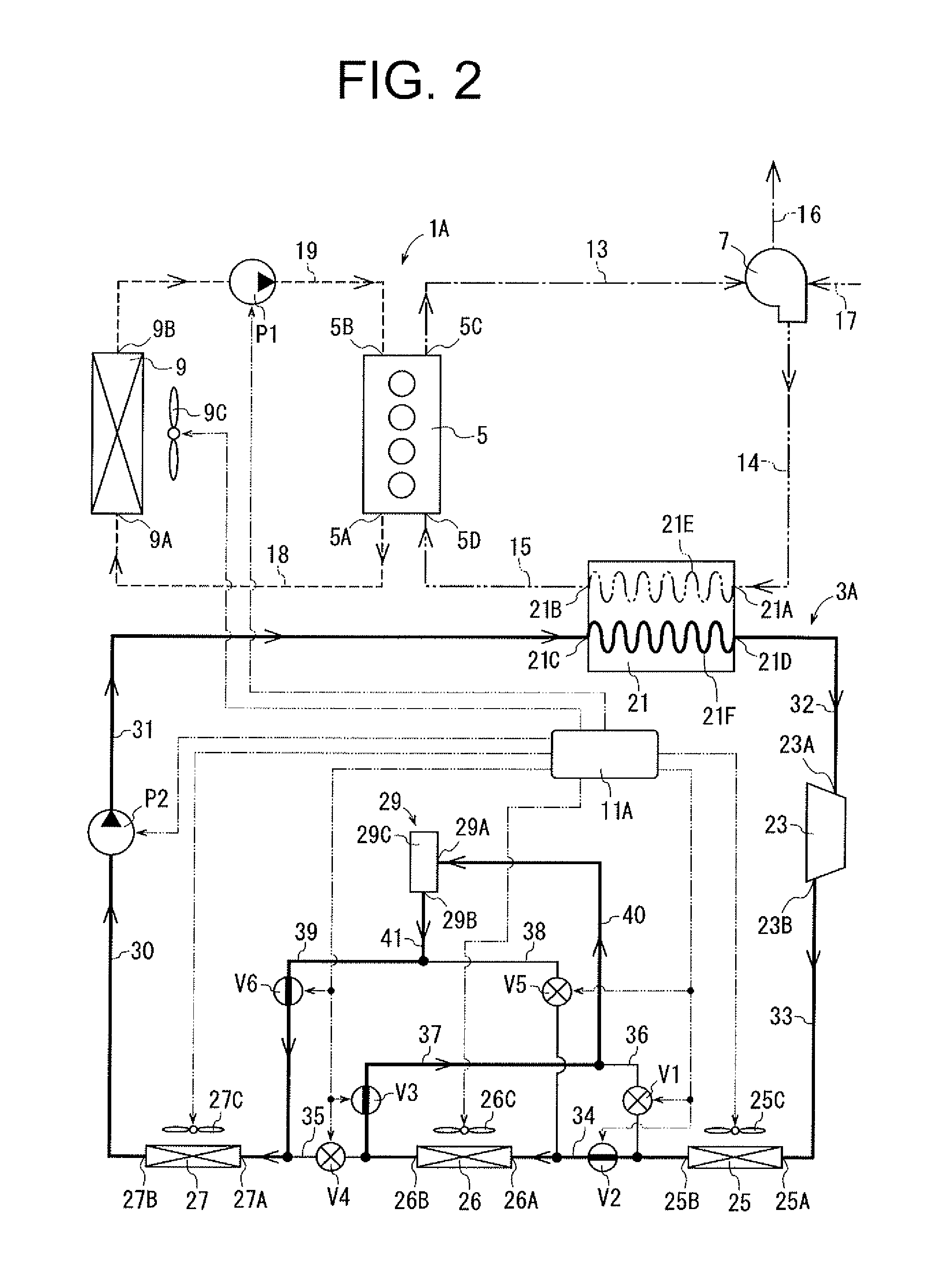
[0072]In the waste heat recovery system of the second embodiment, if the controller 11A determines that the required output of the engine 5 is low and the required cooling load for the compressed air is below a predetermined threshold, the controller 11A causes the valves V2, V3 to be opened and the valve V1, V4 to be closed, as shown in FIG. 5. Working fluid after being cooled in the first and second heat exchangers 25, 26 flows from the tube 35 into the tube 37, and then enters the second receiver 45 through the inlet 45A. Liquid phase working fluid exiting the second receiver 45 through the outlet 45B flows through the tube 39 into the tube 35, and then enters the third heat exchanger 27 through the inlet 27A. That is, the working fluid exiting the outlet 26B of the second heat exchanger 26 enters the third heat exchanger 27 while bypassing the valve V4 provided in the tube 35. In this case, the first and second heat exchangers 25, 26 function as a condenser, and the third heat e...

third embodiment

[0097]Thus, also the waste heat recovery system of the third embodiment can selectively give priority to increasing the recovery of electric power in the Rankine cycle device 3A or increasing the output of the engine 5.

[0098]FIGS. 10, 11 and 12 show the fourth embodiment of the waste heat recovery system according to the present invention. The fourth embodiment differs from the third embodiment in that a subcool condenser 69 is used instead of the subcool condenser 47 of the third embodiment. An electrically operated fan 69C is provided adjacent to the subcool condenser 69 and electrically connected to the controller 11A.

[0099]As shown in FIGS. 10 and 11, the subcool condenser 69 has vertically extending first and second heads 71, 73, tubes 75A to 75L extending horizontally between the first and the second heads 71, 73, a receiver 77, a piston 79 and a driver 81. The piston 79 and the driver 81 correspond to the volume change device and the selector device of the present invention.

[...


PUM


Abstract

The waste heat recovery system includes a Rankine cycle device in which working fluid circulates through a pump, a boiler, an expander and then through a heat exchanging device, heat exchange occurs in the boiler between the working fluid and intake fluid that is introduced into an internal combustion engine while being cooled. The heat exchanging device includes a condenser condensing the working fluid, a receiver connected downstream of the condenser and storing liquid-phase working fluid, a subcooler connected downstream of the receiver and subcooling the liquid-phase working fluid, and a selector device serving to change the ratio of the condenser to the subcooler. The waste heat recovery system further includes a determination device for determining required cooling load for the intake fluid, and a controller for controlling the selector device depending on the required cooling load determined by the determination device.

Description

BACKGROUND OF THE INVENTION[0001]The present invention relates to a waste heat recovery system.[0002]Japanese Unexamined Patent Application Publication No. 2008-8224 discloses a waste heat recovery system used with a power unit and having a Rankine cycle device in which working fluid circulates. The power unit has an internal combustion engine and a turbocharger. The turbocharger supplies compressed air to the engine. The Rankine cycle device has a pump, a compressed air boiler, a coolant boiler, an expander, a condenser and a tube. Working fluid is circulated through the pump, the compressed air boiler, the coolant boiler, the expander and the condenser which are connected by the tube.[0003]Japanese Unexamined Patent Application Publication No. 2007-239513 discloses another waste heat recovery system used with a power unit and having a Rankine cycle device in which working fluid circulates. The power unit has an internal combustion engine and an exhaust gas recirculation passage th...

Claims


Application Information

Patent Timeline
Patent Type & Authority Applications(United States)
IPC IPC(8): F02G3/00
CPCF01K23/065Y02T10/121F28D1/05325F28D21/0003F28D2021/0084F28F2009/0285F28D2021/0082Y02T10/166F01K23/10F02B29/0493F02G5/04F02M25/0738F28F9/0202F28F27/02F02G5/00F02B29/0406F02M25/0731Y02T10/146F28D1/0417F02M26/28F02M26/33Y02T10/12
Inventor ISHIGURO, FUMIHIKOIGUCHI, MASAOMORI, HIDEFUMIENOKIJIMA, FUMINOBU
Owner TOYOTA IND CORP
Why Eureka
Try Eureka