Fuel injector and swirler assembly with lobed mixer

a technology which is applied in the direction of machines/engines, mechanical equipment, lighting and heating apparatus, etc., can solve the problems of increasing pressure drop, high no/sub>x /sub>emission, and poor mixing between air and fuel, so as to improve the mixing rate and improve the effect of fuel injector and swirler

Inactive Publication Date: 2013-03-21
SIEMENS AG
View PDF3 Cites 34 Cited by
  • Summary
  • Abstract
  • Description
  • Claims
  • Application Information

AI Technical Summary

Benefits of technology

[0004]An object of the invention is to provide a fuel injector and swirler assembly with an improved mixing rate between air and fuel. Another object of the invention is to provide a combustion system allowing the combustor to operate i

Problems solved by technology

The fact of having such a large volumetric flow for the synthesis gas poses serious problems in firing them in a premixed mode.
Another problem arising is the different reactivity of these fuels which can be different from natural gas; especially when there is a significant fraction of hydrogen the reactivity tends to be high, and this constitutes a problem as it aggravates the danger of flashback.
These translate into the fact that a much larger fuel flow through the air passages leads to an increase in pressure drop, and that mixing between the air and fuel tends to be poor.
The latest is mainly d

Method used


Image

  • Fuel injector and swirler assembly with lobed mixer
  • Fuel injector and swirler assembly with lobed mixer
  • Fuel injector and swirler assembly with lobed mixer

Examples


Embodiment Construction

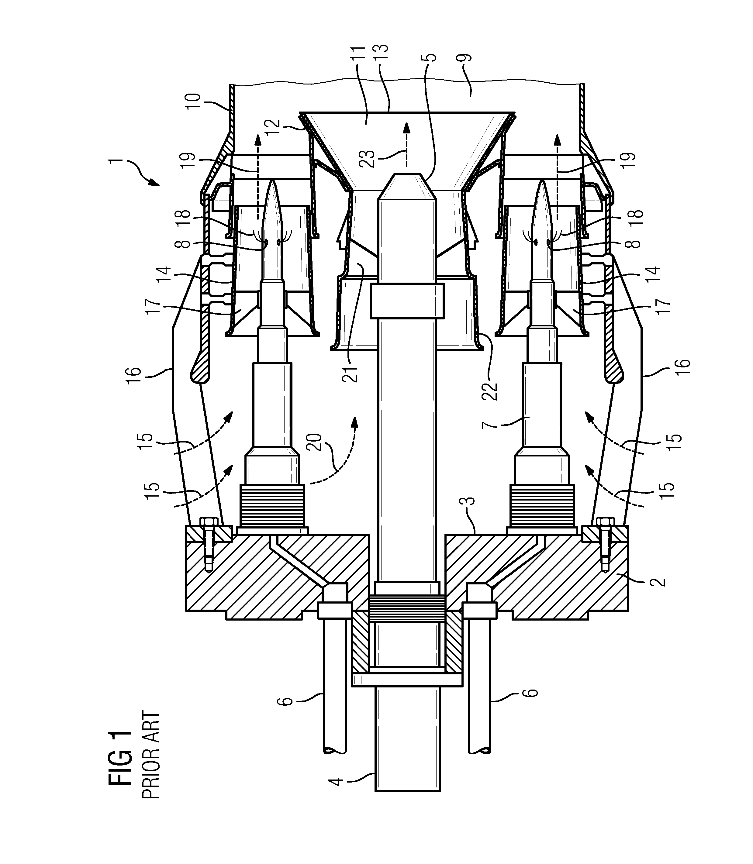
[0032]FIG. 1 shows an example of a prior art gas turbine combustor 1, some aspects of which may be applied to the present invention. A housing base 2 has an attachment surface 3. A pilot fuel delivery tube 4 has a pilot fuel diffusion nozzle 5. Fuel inlets 6 provide a main fuel supply to main fuel delivery tube structures 7 with injection ports 8. A main combustion zone 9 is formed within a liner 10 downstream of a pilot flame zone 11. A pilot cone 12 has a divergent end 13 that projects from the vicinity of the pilot fuel diffusion nozzle 5 downstream of main fuel injector and swirler assemblies 14. The pilot flame zone 11 is formed within the pilot cone 12 adjacent to and upstream of the main combustion zone 9.

[0033]Compressed air 15 from a compressor (not shown) flows between support ribs 16 through the swirler assemblies 14. Within each main swirler assembly 14, a plurality of swirler vanes 17 generate air turbulence upstream of main fuel injection ports 8 to mix compressed air ...


PUM


Abstract

Disclosed is a gas turbine fuel injector and swirler assembly, including: a delivery tube structure arranged on a central axis of the fuel injector and swirler assembly, a first fuel supply channel arranged in the delivery tube structure, a shroud surrounding the delivery tube structure, swirl vanes arranged between the delivery tube structure and the shroud, a radial passage in each swirl vane, communicating with the first fuel supply channel, a set of apertures open between the radial passage and the exterior surface of said each swirl vane, wherein a second fuel supply channel is arranged in the delivery tube structure extending to a downstream end of the delivery tube structure and a mixer with lobes for fuel injection is arranged at the downstream end. Further disclosed is an assembly method for assembling a fuel injector and swirler assembly.

Description

FIELD OF THE INVENTION[0001]The invention relates to a fuel injector and swirler assembly for a gas turbine. Further, the invention relates to a combustion system. The invention also relates to a gas turbine. In addition, the invention relates to an assembly procedure for assembling a fuel injector and swirler assembly.BACKGROUND OF THE INVENTION[0002]The increase of price of natural gas has pushed the development of gas turbines in the direction of considering alternative fuels such as the so called synthesis gases. These gases typically come from gasification processes of solid feedstock such a coal, pet coke or biomass. The use of synthesis gas in gas turbines involves a much larger volumetric flow injection of fuel than standard natural gas. In order to achieve the very low NOx values that are typical of modern gas turbines it is needed for the combustors to run in premixed mode. The fact of having such a large volumetric flow for the synthesis gas poses serious problems in firi...

Claims


Application Information

Patent Timeline
IPC IPC(8): F02C7/22
CPCF23R3/14F02C7/22F23R3/286
Inventor FOX, TIMOTHY A.WILLIAMS, STEVENWORZ, ULRICHVAN KAMPEN, JAAP
Owner SIEMENS AG
Why Eureka
Try Eureka