Micro electro mechanical systems component

a technology of mechanical systems and components, applied in the direction of turning-sensitive devices, acceleration measurement using interia forces, instruments, etc., can solve the problems of large force applied to the mass body, damage to the supporting parts degrading sensitivity of the mass body, so as to prevent the influence of disturban

Inactive Publication Date: 2013-03-21
SAMSUNG ELECTRO MECHANICS CO LTD
View PDF1 Cites 33 Cited by
  • Summary
  • Abstract
  • Description
  • Claims
  • Application Information

AI Technical Summary

Benefits of technology

[0013]The present invention has been made in an effort to provide an MEMS component capable of preventing an influence of disturbance occurring from external environments or noise or interference from surrounding sensors, by forming a space between a post and a stopper to use a predetermined region of a membrane disposed above the space.

Problems solved by technology

However, the inertial sensor according to the prior art is influenced by disturbance or noise occurring from external environment or interference from surrounding sensors and as a result, sensitivity thereof may be degraded.
In addition, in the inertial sensor according to the prior art, when an excessive force is applied to the mass body, supporting parts of the mass body, for example, the membrane, or the like, may be damaged.
In particular, when the inertial sensor crashes to the ground due to free falling, a very large force is applied to the mass body, such that it is highly likely to damage the supporting part of the mass body.
When the adhesive is permeated into the post, a space between the mass body and the cap is reduced, thereby deteriorating dynamic characteristics of the inertial sensor.
In addition, when an amount of the adhesive permeating into the post is increased, the adhesive is directly bonded to the mass body, thereby causing defects of the inertial sensor.
Although the above-mentioned problems are described based on the inertial sensor, the above-mentioned problems may also occur in the pressure sensor, the oscillator, or the like, having a very similar structure to the inertial sensor among the MEMS components.

Method used


Image

  • Micro electro mechanical systems component
  • Micro electro mechanical systems component
  • Micro electro mechanical systems component

Examples


Embodiment Construction

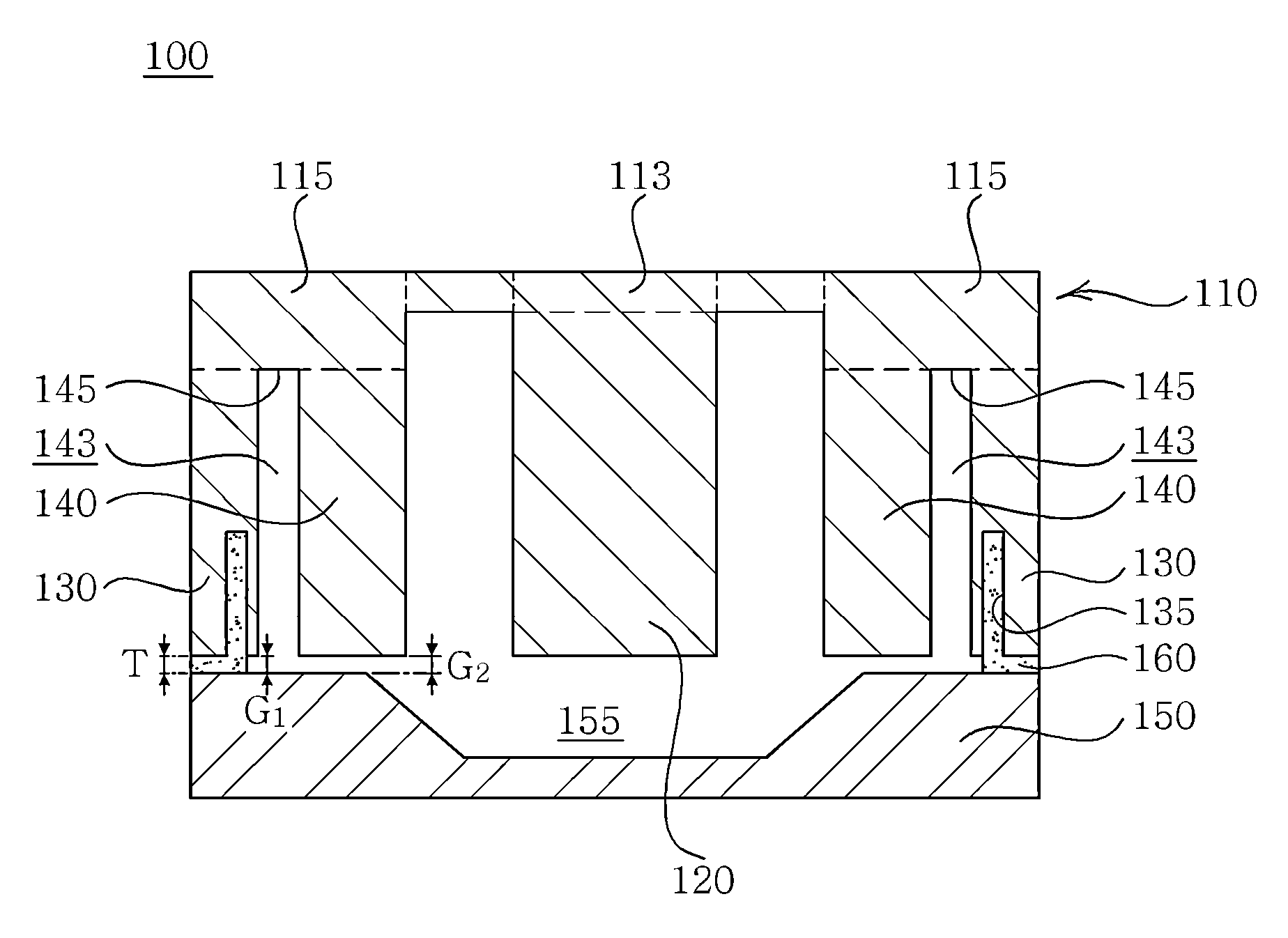
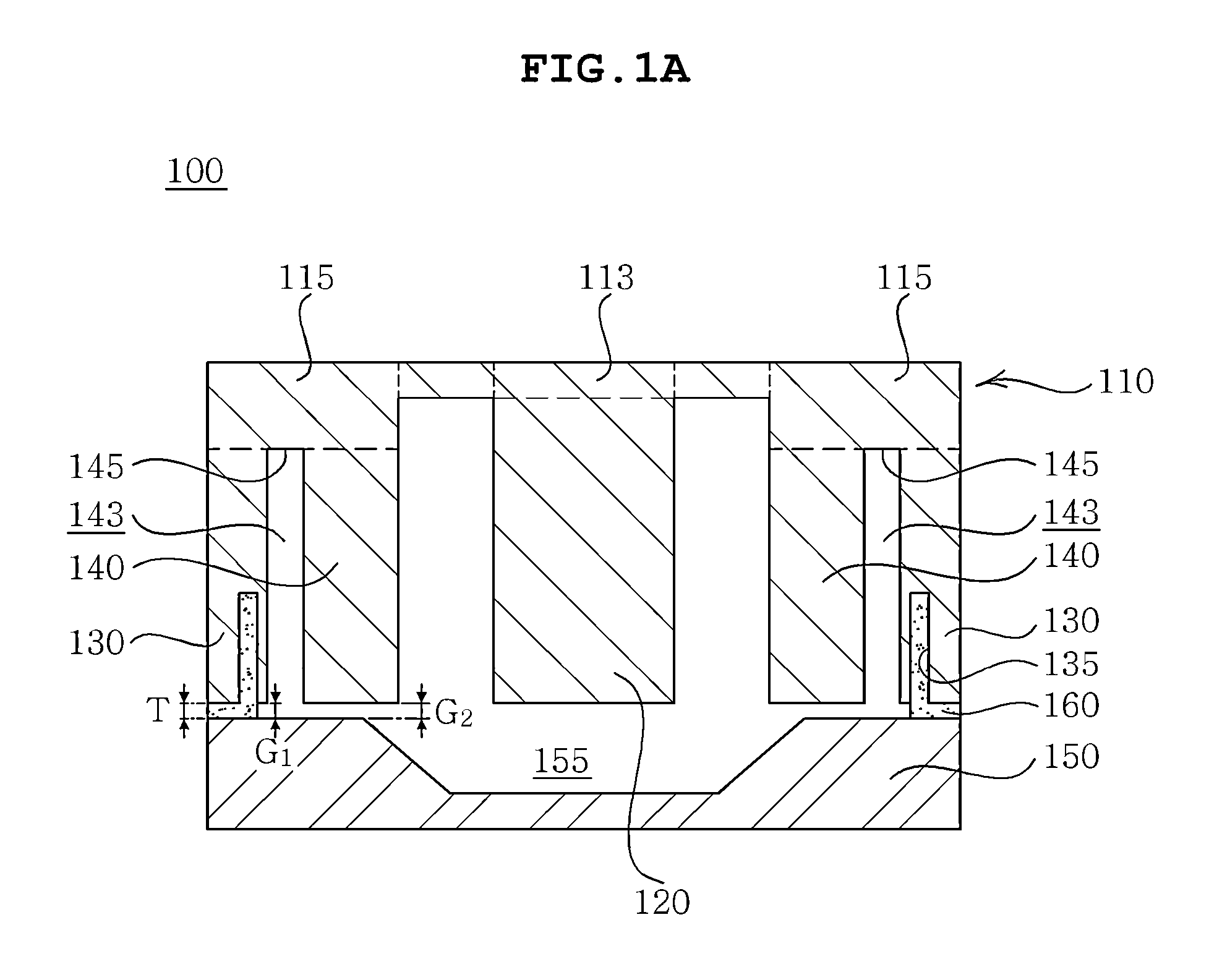
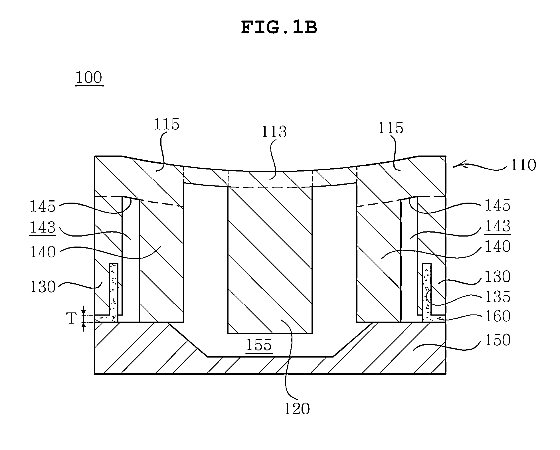
[0036]Various features and advantages of the present invention will be more obvious from the following description with reference to the accompanying drawings.

[0037]The terms and words used in the present specification and claims should not be interpreted as being limited to typical meanings or dictionary definitions, but should be interpreted as having meanings and concepts relevant to the technical scope of the present invention based on the rule according to which an inventor can appropriately define the concept of the term to describe most appropriately the best method he or she knows for carrying out the invention.

[0038]The above and other objects, features and advantages of the present invention will be more clearly understood from the following detailed description taken in conjunction with the accompanying drawings. In the specification, in adding reference numerals to components throughout the drawings, it is to be noted that like reference numerals designate like component...


PUM

PropertyMeasurementUnit
thicknessaaaaaaaaaa
massaaaaaaaaaa
densityaaaaaaaaaa

Abstract

Disclosed herein is a MEMS component. The MEMS component according to the exemplary embodiment of the present invention includes: a plate-shaped membrane 110; a post 130 disposed under an edge 115 of the membrane 110; a stopper 140 disposed under the membrane 110 and disposed more inwardly than the post 130 so as to form a space 143 between the stopper 140 and the post 130; and a cap 150 disposed under the post 130 so as to cover the post 130, whereby the influence of disturbance or noise occurring from external environments or interference from surrounding sensors can be interrupted by using a predetermined region 145 of the membrane 110 disposed above the space 143.

Description

CROSS REFERENCE TO RELATED APPLICATION[0001]This application claims the benefit of Korean Patent Application No. 10-2011-0092898, filed on Sep. 15, 2011, entitled “Micro Electro Mechanical Systems Component”, which is hereby incorporated by reference in its entirety into this application.BACKGROUND OF THE INVENTION[0002]1. Technical Field[0003]The present invention relates to an MEMS component.[0004]2. Description of the Related Art[0005]Micro electro mechanical systems (MEMS) are a technology of manufacturing an ultra-fine machine structure, such as a ultra-high density integrated circuit, an inertial sensor, a pressure sensor, an oscillator, or the like, by machining silicon, crystal, glass, or the like. The MEMS component has a precision of micrometer ( 1 / 1,000,000 meter) or less and structurally uses a semiconductor micro manufacturing technology that repeats processes, such as deposition, etching, or the like, thereby mass-producing micro products at low costs.[0006]An inertial...

Claims


Application Information

Patent Timeline
Patent Type & Authority Applications(United States)
IPC IPC(8): G01P15/097H03B5/30G01L11/00
CPCH03B5/30G01C19/56G01P15/08G01P2015/084G01L9/0047G01P2015/0871G01L9/0048H03H9/2405G01P15/14B81B3/00G01C19/5621G01P15/097
Inventor JEUNG, WON KYUKIM, JONG WOONPARK, HEUNG WOO
Owner SAMSUNG ELECTRO MECHANICS CO LTD
Why Eureka
Try Eureka