White Organic Light Emitting Device

a light-emitting device and organic technology, applied in the direction of organic semiconductor devices, thermoelectric devices, solid-state devices, etc., can solve the problems of large color difference upon low current operation, fluorescent stack exhibits relatively low efficiency, and fluorescent stacks exhibit relatively low efficiency

Active Publication Date: 2013-03-21
LG DISPLAY CO LTD
View PDF18 Cites 34 Cited by
  • Summary
  • Abstract
  • Description
  • Claims
  • Application Information

AI Technical Summary

Benefits of technology

[0023]The first hole transport layer may further include a first blocking layer adjacent to the first light emitting layer, to prevent introduction of electrons or excitons into the first l

Problems solved by technology

In this regard, when a white organic light emitting device having a laminate structure including a fluorescent stack and a phosphorescent stack is formed, the fluorescent stack exhibits a relatively low efficiency.
As a result, great difference in color upon operation at low current occurs.
These conventional white organic light emitting devices have the following problems.
W

Method used


Image

  • White Organic Light Emitting Device
  • White Organic Light Emitting Device
  • White Organic Light Emitting Device

Examples


Embodiment Construction

[0039]Reference will now be made in detail to the specific embodiments of the present invention, examples of which are illustrated in the accompanying drawings.

[0040]Hereinafter, a white organic light emitting device according to the present invention will be described in detail with reference to the accompanying drawings.

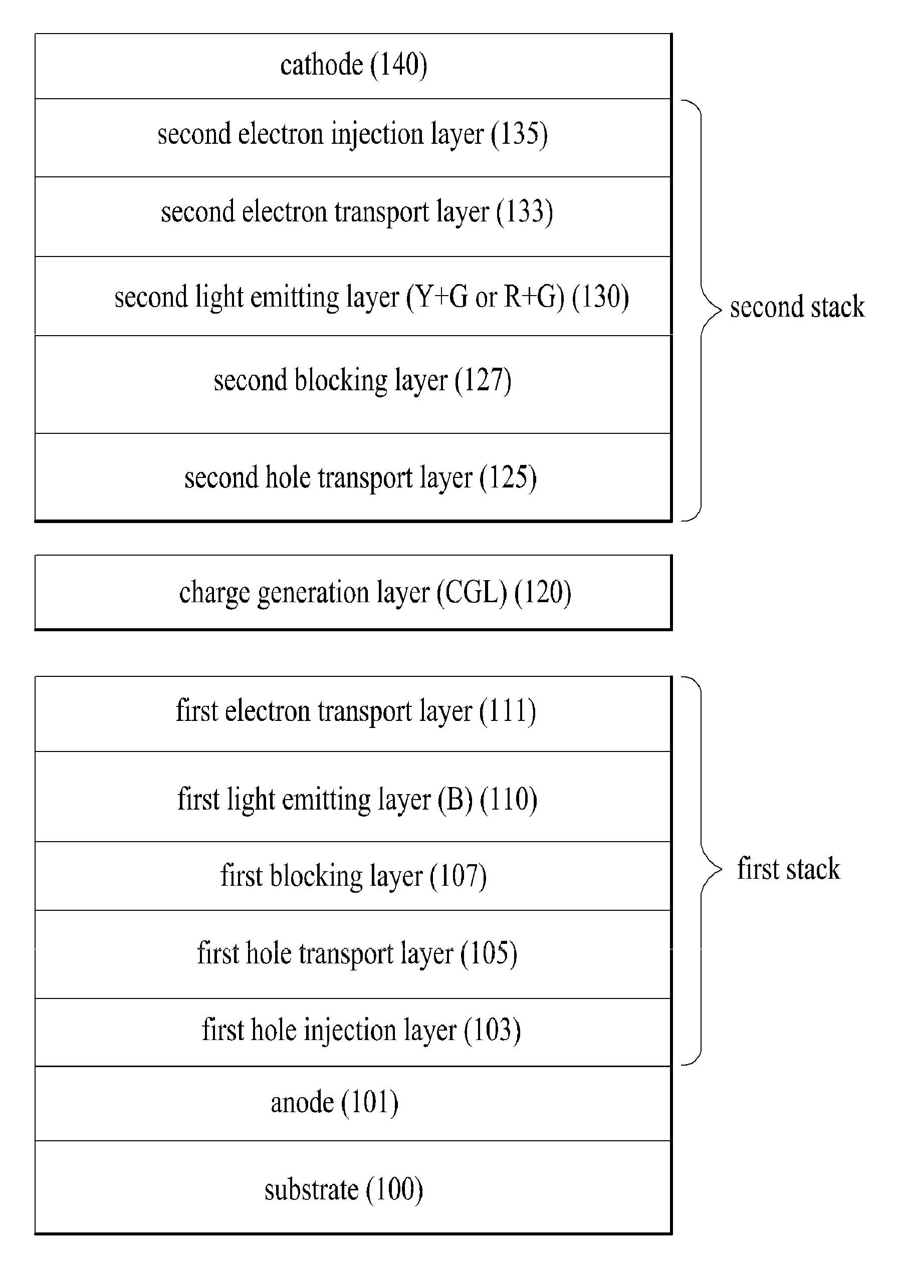
[0041]FIG. 1 is a sectional view illustrating a white organic light emitting device according to the present invention.

[0042]As shown in FIG. 1, the white organic light emitting device according to the present invention includes a substrate 100, an anode 101 and a cathode 140 that face each other on the substrate 100, a first stack laminated between the anode 101 and the cathode 140, a charge generation layer 120 and a second stack.

[0043]The anode 101 is formed of a transparent electrode material such as indium tin oxide (ITO) and the cathode 140 is formed of a reflective metal such as aluminum (Al). According to the light emission effects occurring in the first an...


PUM


Abstract

Disclosed white organic light emitting device includes an anode and a cathode opposing each other; a charge generation layer interposed between the anode and the cathode; a first stack interposed between the anode and the charge generation layer, the first stack including a first hole transport layer and a first light emitting layer emitting blue fluorescent light; and a second stack interposed between the charge generation layer and the cathode, the second stack including a second hole transport layer and a second light emitting layer formed by doping one host with at least one of phosphorescent dopant, wherein a triplet energy level of the first hole transport layer is higher than a triplet energy level of the first light emitting layer, and a hole mobility of the first hole transport layer is 5.0×10⁻⁴ cm2/s·V to 9.9×10⁻³ cm2/s·V.

Description

[0001]This application claims the benefit of Korean Patent Application No. P 10-2011-0094917, filed on Sep. 20, 2011 and Korean Patent Application No. P 10-2012-0086566, filed on Aug. 8, 2012, both of which are hereby incorporated by reference as if fully set forth herein.BACKGROUND OF THE INVENTION[0002]1. Field of the Invention[0003]The present invention relates to an organic light emitting device. More specifically, the present invention relates to a white organic light emitting device in which the efficiency of a blue fluorescent stack is improved to be similar to that of a phosphorescent stack.[0004]2. Discussion of the Related Art[0005]The recent trend toward information-dependent age has brought about rapid development in display fields in which electrical information signals are visually displayed. In this regard, a variety of flat display devices having superior properties such as slimness, low weight and low power consumption have been developed and are actively used as su...

Claims


Application Information

Patent Timeline
IPC IPC(8): H01L33/26
CPCH01L51/5004H01L51/5016H01L51/5278H01L51/5096H01L2251/5376H01L2251/55H01L27/3209H10K59/32H10K50/11H10K2101/40H10K50/18H10K2101/10H10K50/19H10K2101/27H10K2101/00
Inventor SONG, KI-WOOGPIEH, SUNG-HOONKO, SUNG-JAE
Owner LG DISPLAY CO LTD
Why Eureka
Try Eureka