
Multi-carrier Optical Communication Method and System Based on DAPSK

a communication method and optical communication technology, applied in the field of optical fiber communication, can solve the problems of increasing data redundancy, reducing spectrum efficiency, and difficult problems caused by optical fiber nonlinearity, so as to improve the tolerance of existing optical communication systems, reduce spectrum efficiency, and enhance the system's resistance.

Active Publication Date: 2013-03-21
BEIJING UNIV OF POSTS & TELECOMM
View PDF4 Cites 20 Cited by
  • Summary
  • Abstract
  • Description
  • Claims
  • Application Information

AI Technical Summary

Benefits of technology

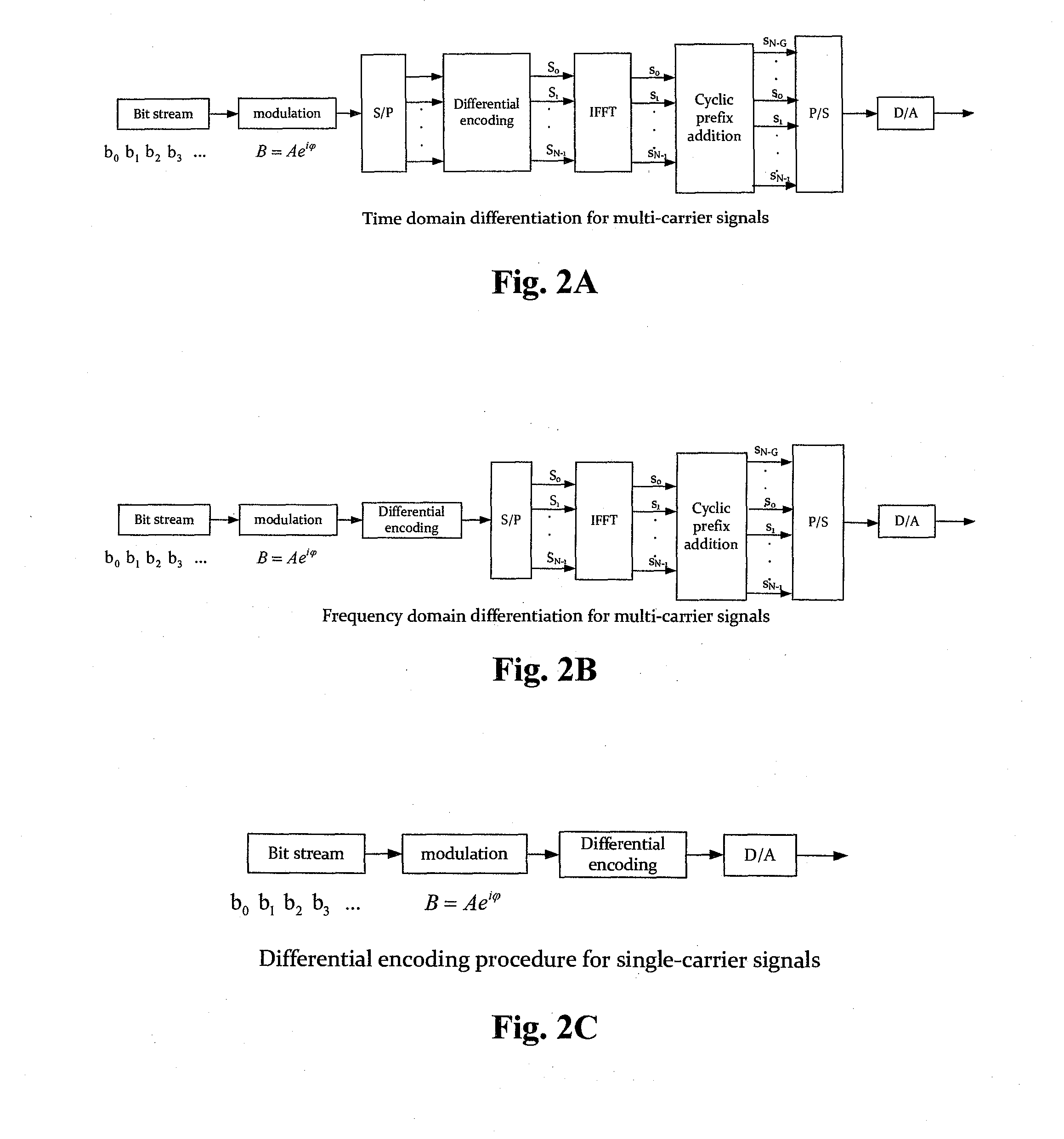
The present invention provides a method and system for optical communication that can enhance the system's ability to resist inter-carrier interference without reducing spectrum efficiency. This improves the tolerance of optical communication systems for various damages and improves the performance of the communication system. The differential encoding based optical communication system utilizes differential modulation at the signal transmitter to achieve this. The invention also avoids the need for known data such as training symbols and pilot sub-carriers for compensating algorithms such as channel estimation and greatly improves the system's effective speed and spectrum efficiency.

Problems solved by technology

In an optical OFDM system which is a present research hotspot, since OFDM signals obtained by using a conventional modulation technique have a higher peak-power ratio, effects caused by optical fiber nonlinearity become a tough problem.
As for conventional PSK or QAM encoded OFDM signals, known data such as training symbols, pilot sub-carriers or a separately inserted radio frequency signal is used to perform channel estimation, phase noise compensation and so on, which on one hand increases data redundancy and reduces spectrum efficiency, on the other hand increases the complexity of the digital signal processing at the receiver.

Method used


Image

  • Multi-carrier Optical Communication Method and System Based on DAPSK
  • Multi-carrier Optical Communication Method and System Based on DAPSK
  • Multi-carrier Optical Communication Method and System Based on DAPSK

Examples


Embodiment Construction

[0045]Hereinbelow, embodiments of the present invention will be described with reference to the accompanying drawings. It is understood that described embodiments are only some of, not all of, the embodiments of the present invention. All other embodiments obtained by those ordinary skills in the art on the basis of the embodiments in the present invention and without any creative labor belong to the protection scope of the present invention.

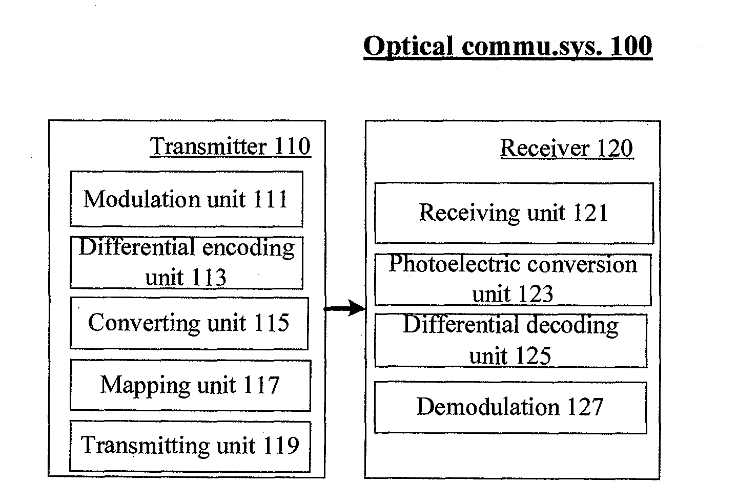
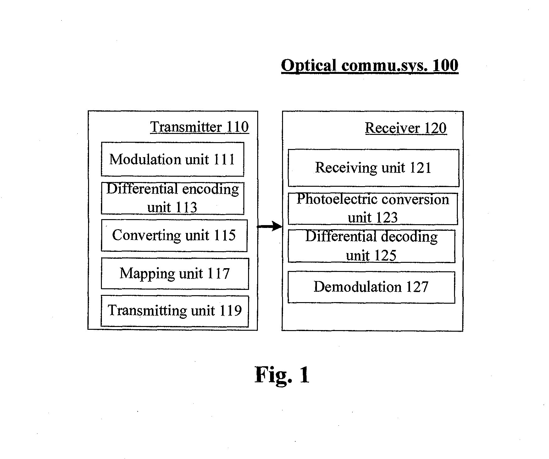
[0046]In order to enhance capability to resist inter-carrier interference without decreasing spectrum efficiency, the optical communication system according to the present invention may perform encoding at the transmitter on the bit stream data to be transmitted by using a differential encoding technique and have the resultant differentially encoded electrical signals modulated onto optical carriers to generate optical signals for transmission, and may perform decoding at the receiver on the received optical signals by using a corresponding diff...


PUM


Abstract

The present invention provides an optical communication method, comprising: performing modulation on the obtained bit stream data to generate modulated signals; performing differential encoding on the modulated signals to generate differentially encoded signals; converting the differentially encoded signals into electrical signals; and mapping the electrical signals onto optical carriers to generate optical signals for transmission. With the present invention, it is possible to enhance the system's capability of resisting inter-carrier interference without decreasing spectrum efficiency, hence improving the tolerance of existing optical communication systems towards laser linewidth, fast-changing PMD, optical fiber nonlinearity, inter-channel interference and other damages, greatly enhancing system performances.

Description

TECHNICAL FIELD[0001]The present invention relates to optical fiber communication field, more particularly to an optical communication method and a system based on differential encoding.BACKGROUND[0002]Multi-carrier technology has been proposed in order to enhance the spectrum efficiency of a light transmitting system. Up to date, this technology mainly uses WDM, OFDM and Superchannel proposed by Bell Laboratory in 2010.[0003]Among them, WDM is the English abbreviation for wavelength division multiplexing, in which the carrier separation is generally on the order of tens GHz. OFDM is the English abbreviation for orthogonal frequency division multiplexing, and was introduced into the optical communication field from the wireless communication field. Up to date, OFDM may be divided into traditional OFDM, in which OFDM signals generated in electrical domain are loaded onto optical carriers and thus the sub-carrier separation is small and usually on the order of MHz, and all-optical OFD...

Claims


Application Information

Patent Timeline
IPC IPC(8): H04L27/00H04B10/06H04L27/28H04B10/04H04L27/36
CPCH04L27/36H04L1/0061H04L27/2071
Inventor WU, JIANWANG, HUILL, YANHONG, XIAOBINGUO, HONGXIANGZUO, YONGXU, KUNLL, WEILIN, JINTONG
Owner BEIJING UNIV OF POSTS & TELECOMM
Learn More