Virtual core router and switch systems and methods with a hybrid control architecture

a router and switch technology, applied in the field of virtual router/switch systems, can solve the problems of not being deployed in practice in carrier ip network, interoperability of routing protocols, and multilayer control mechanisms such as generalized multi-protocol label switching (gmpls)

Active Publication Date: 2013-03-21
CIENA
View PDF3 Cites 53 Cited by
  • Summary
  • Abstract
  • Description
  • Claims
  • Application Information

AI Technical Summary

Benefits of technology

[0006]In yet another exemplary embodiment, a method includes operating a plurality of edge routers; interconnecting the plurality of edge routers between one another through a virtual device, the virtual device including a plurality of interconnected optical switches and a packet controller communicatively coupled to the plurality of interconnected optical switches; operating a distributed control plane for transport switching functions on the plurality of interconnected optical switches; and operating a centralized control plane for packet switching functions on the plurality of interconnected optical switches. The method may further include peering between the plurality of edge routers and the virtual device such that the plurality of edge routers are not required to maintain routing adjacencies between one another. The method may further include implementing the virtual device though the plurality of interconnected optical switches and the packet controller to remove core routers between the plurality of edge routers.

Problems solved by technology

As a result, multilayer control mechanisms such as Generalized Multi-Protocol Label Switching (GMPLS) (e.g., as defined by the Internet Engineering Task Force (IETF) in Requests for Comment (RFC) 3945, RFC 3471, RFC 3209, RFC 3479, etc., the contents of each are incorporated by reference herein) have not been deployed in practice in carrier IP networks.
However, directly connecting the edge routers 110 at an IP level results in a full mesh of connectivity between the edge routers 110, and introduces a significant penalty at the IP level to maintain adjacencies with every other edge router 110.
Furthermore, interoperability of the routing protocols adds another constraint.
This creates a strong requirement that router software be interoperable and consistent, making it very difficult to introduce new functions or to allow a carrier to introduce a new IP vendor because of the risk of introducing routing problems.

Method used


Image

  • Virtual core router and switch systems and methods with a hybrid control architecture
  • Virtual core router and switch systems and methods with a hybrid control architecture
  • Virtual core router and switch systems and methods with a hybrid control architecture

Examples


Embodiment Construction

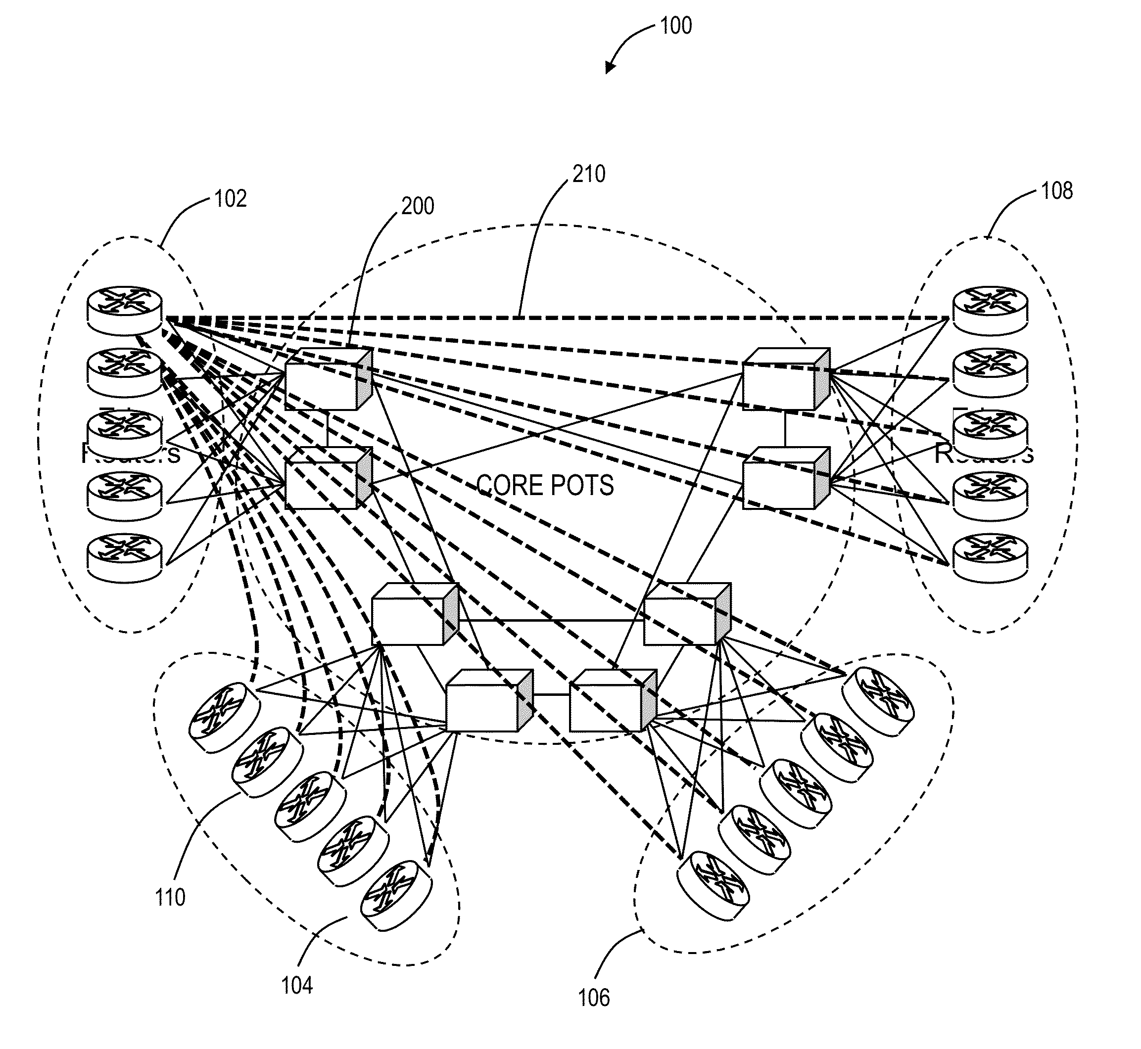
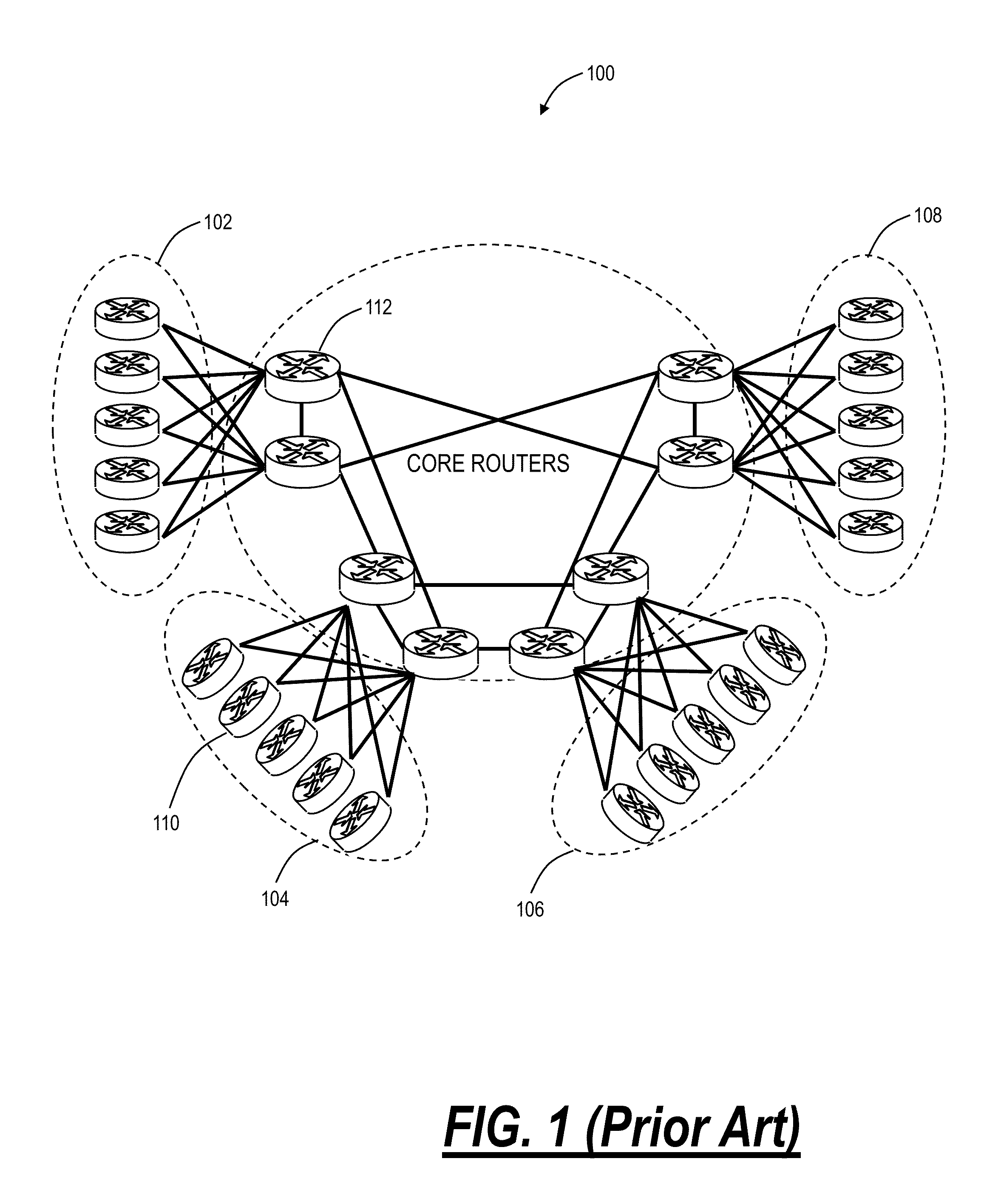
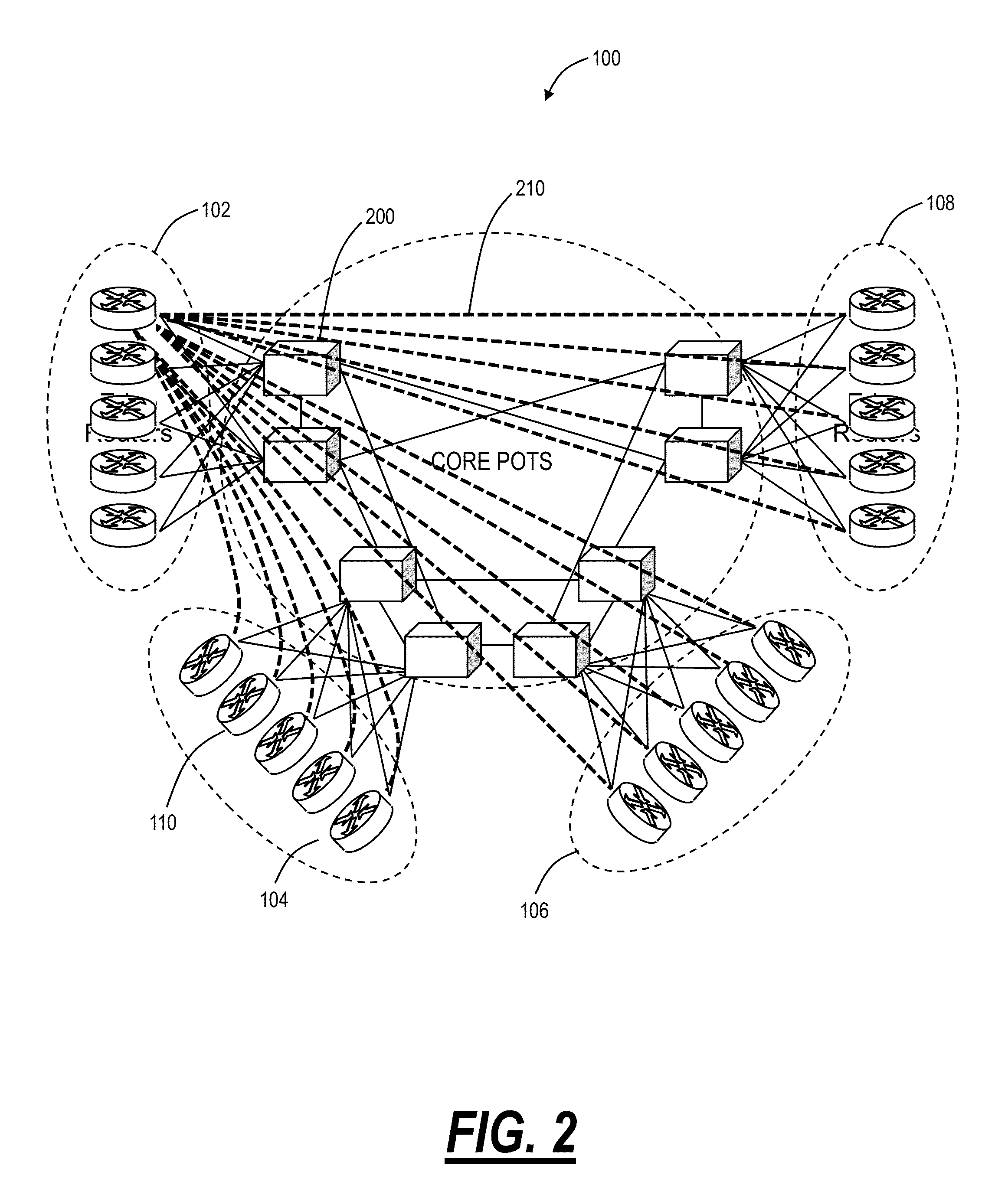
[0021]In various exemplary embodiments, the present invention relates to virtual router / switch systems and methods with a domain of optical switches operating as a single, virtualized router / switch using a control plane design combining centralized control of higher layer packet switching functions with distributed control over transport switching functions. The virtual router / switch systems and methods simplify and reduce cost of IP networks by removing the core routers 112, replacing them with lower cost, high capacity optical switches which are Packet Optical Transport Systems (POTS). The virtual router / switch systems and methods further avoid full mesh connectivity of the edge routers 110 and the associated need to maintain routing adjacencies to each of the other edge routers 110. In addition, the core can be converted to the POTS without requiring new control plane functionality from the edge routers 110, such as support of Multi-Protocol Label Switching (MPLS) Label Switch Pa...


PUM


Abstract

The present disclosure provides virtual router/switch systems and methods with a domain of optical switches operating as a single, virtualized router using a control plane design combining centralized control of higher layer packet switching functions with distributed control over transport switching functions. The virtual router systems and methods simplify and reduce cost of Internet Protocol (IP) networks by removing the core routers, replacing them with lower cost, high capacity optical switches which are Packet Optical Transport Systems (POTS). The virtual router systems and methods avoids full mesh connectivity of the edge routers and the associated need to maintain routing adjacencies to each of the other edge routers. The virtual router systems and methods include a centralized IP layer management. Further, the virtual router systems and methods include distributed control of the optical layers.

Description

FIELD OF THE INVENTION[0001]The present invention relates generally to networking systems and methods. More particularly, the present invention relates to virtual router / switch systems and methods with a domain of optical switches operating as a single, virtualized router / switch using a control plane design combining centralized control of higher layer packet switching functions with distributed control over transport switching functions.BACKGROUND OF THE INVENTION[0002]Referring to FIG. 1, conventionally, carrier Internet Protocol (IP) networks such as an exemplary network 100 are organized in tiers, where the lower tiers 102, 104, 106, 108 include edge routers 110 that connect to larger core routers 112. The edge routers 110 perform numerous IP protocol functions, whereas the core routers 112 are mostly called upon to forward traffic from one edge router 110 to another. Also, adjacent routers 110, 112 all support the same set of IP protocols. Currently, the lower layers supporting...

Claims


Application Information

Patent Timeline
Patent Type & Authority Applications(United States)
IPC IPC(8): H04J14/00H04L45/42H04L45/586
CPCH04L45/586H04L45/62H04L49/357H04J11/0066H04L49/60H04L45/04H04L45/42
Inventor ONG, LYNDON Y.
Owner CIENA
Why Eureka
Try Eureka