System and method for magnetic current density imaging at ultra low magnetic fields

Inactive Publication Date: 2013-03-21
TRIAD NAT SECURITY LLC
View PDF7 Cites 21 Cited by
  • Summary
  • Abstract
  • Description
  • Claims
  • Application Information

AI Technical Summary

Benefits of technology

[0004]Various imaging techniques have been developed for the investigation of biological and other specimens. Some of these techniques (for example, magnetic resonance imaging and positron emission tomography) have become routine in clinical applications. Most imaging techniques rely on particular specimen properties to produce image contrast. For example, magnetic resonance images can depend on specimen spin T1 or T2 relaxation times, or spin densities. Magnetic resonance imaging has also been applied to so-called functional imaging (functional MRI or fMRI) so that magnetic resonance images can be associated with specimen brain function related to blood flow or oxygenation and not merely with specimen structure. Unfortunately, most magnetic resonance imaging systems require application of very high magnetic fields (1 Tesla or more), and thus require expensive, complex magnets. In addition, these high magnetic fields are problematic for clinical measurements of other types, due to the undesirable effects of large magnetic fields on other instrumentation that might be necessary for specimen measurements. In addition, while such magnetic resonance imaging methods generally have spatial resolution on the scale of millimeters (mm), they have poor temporal resolution, typically, no better than a few seconds. However, imaging methods in clinical and other applications can typically be selected to provide high spatial resolution images that lack high temporal resolution dynamic functional information, or to provide high temporal resolution functional information that cannot be readily associated with any specimen features or locations. Unfortunately, the use of magnetic resonance imaging in combination with other clinical measurement techniques is genera

Problems solved by technology

Unfortunately, most magnetic resonance imaging systems require application of very high magnetic fields (1 Tesla or more), and thus require expensive, complex magnets.
In addition, these high magnetic fields are problematic for clinical measurements of other types, due to the undesirable effects of large magnetic fields on other instrumentation that might be necessary for specimen measurem

Method used


Image

  • System and method for magnetic current density imaging at ultra low magnetic fields
  • System and method for magnetic current density imaging at ultra low magnetic fields
  • System and method for magnetic current density imaging at ultra low magnetic fields

Examples


Embodiment Construction

[0013]The following description of the preferred embodiments of the present invention and variations thereof is made with reference to the Figures and one or more illustrative example configurations and / or implementations. Those of skill in the art will recognize that the following description is for illustrative purposes only, and that the scope of the present invention is defined exclusively by the following claims.

Preferred System

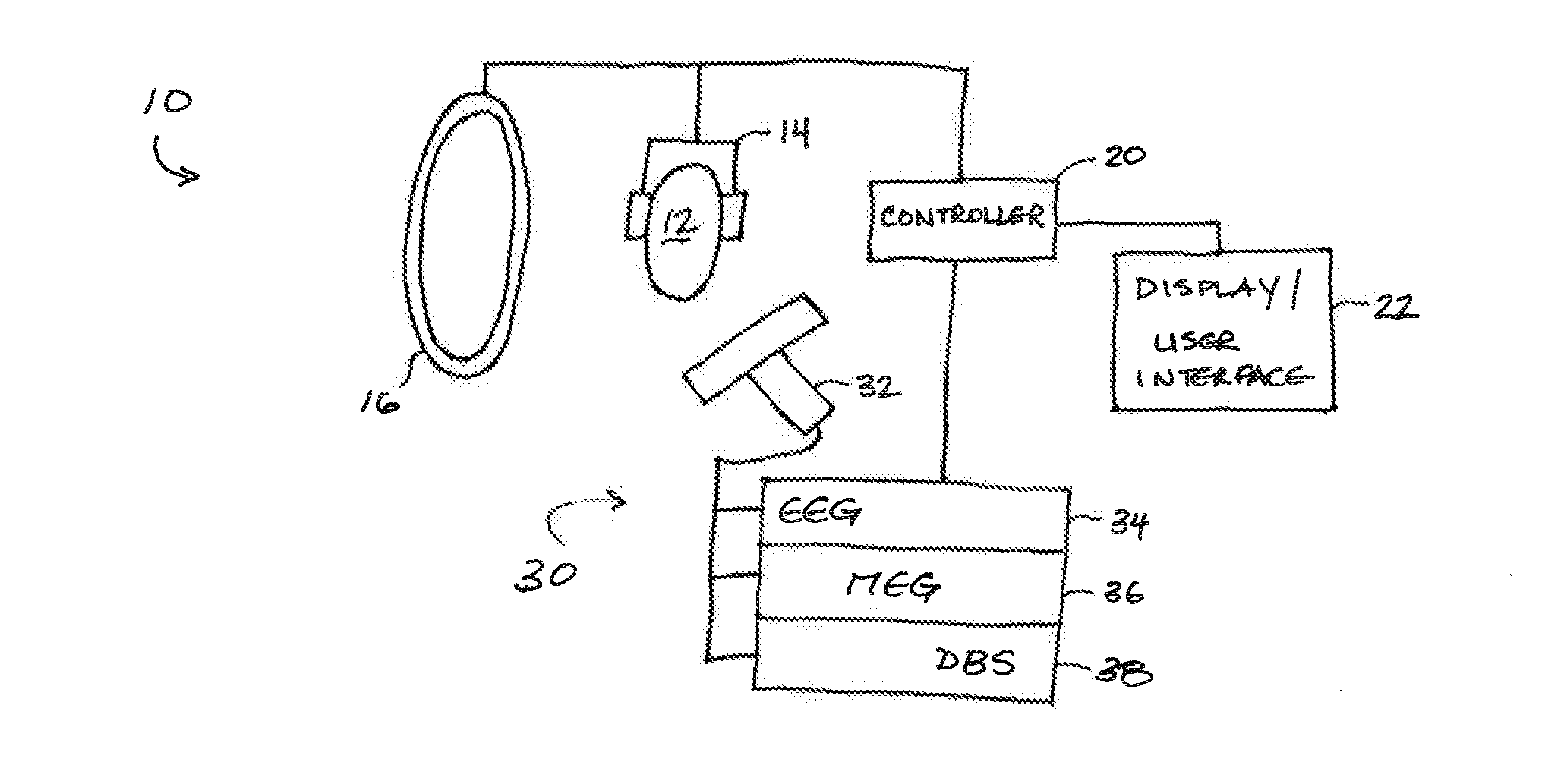
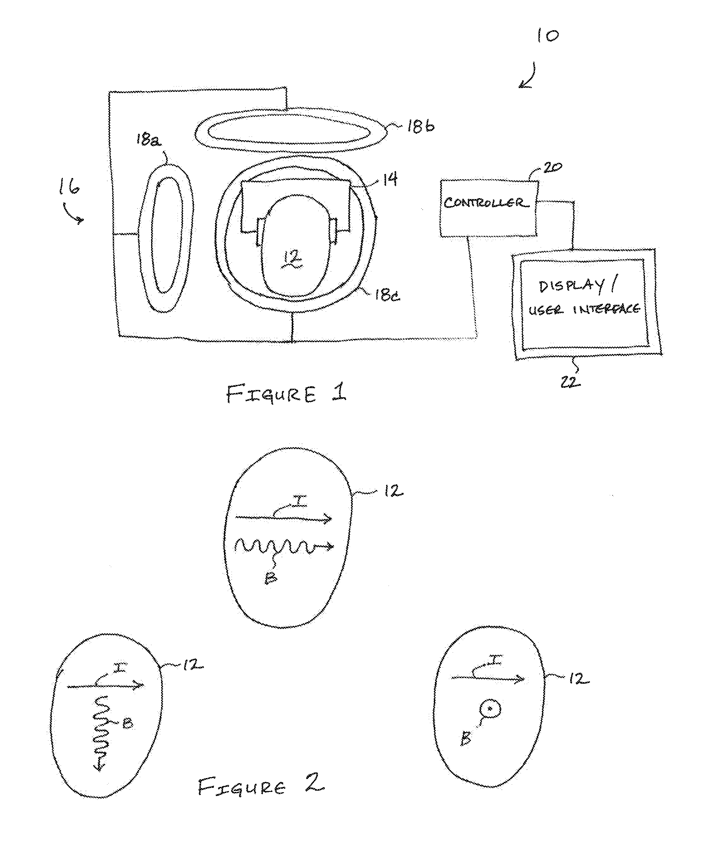
[0014]As shown in FIG. 1, a preferred system 10 can include an electrical impedance tomography apparatus 14 electrically connectable to an object 12; an ultra low field magnetic resonance imaging apparatus 16 including a plurality of field directions and disposable about the object 12; a controller 20 connected to the ultra low field magnetic resonance imaging apparatus 16 and configured to implement a sequencing of one or more ultra low magnetic fields substantially along one or more of the plurality of field directions; and a display 22 connected to th...


PUM


Abstract

Preferred systems can include an electrical impedance tomography apparatus electrically connectable to an object; an ultra low field magnetic resonance imaging apparatus including a plurality of field directions and disposable about the object; a controller connected to the ultra low field magnetic resonance imaging apparatus and configured to implement a sequencing of one or more ultra low magnetic fields substantially along one or more of the plurality of field directions; and a display connected to the controller, and wherein the controller is further configured to reconstruct a displayable image of an electrical current density in the object. Preferred methods, apparatuses, and computer program products are also disclosed.

Description

CLAIM OF PRIORITY[0001]The present application claims priority to U.S. Provisional Patent Application Ser. No. 61 / 536,482 filed on 19 Sep. 2011 and entitled “Magnetic Resonance Current Density Imaging and Electrical Impedance Tomography at Ultra-low Magnetic Fields,” and to U.S. Provisional Patent Application Ser. No. 61 / 674,129 filed on 20 Jul. 2012 and entitled “Ultra-low Field Functional Magnetic Resonance Combined with Magneto-encephalography,” the entirety of both of which are incorporated herein by this reference.STATEMENT REGARDING FEDERAL RIGHTS[0002]The United States government has rights in this invention pursuant to Contract No. DE-AC52-06NA25396 between the United States Department of Energy and Los Alamos National Security, LLC for the operation of Los Alamos National Laboratory.TECHNICAL FIELD[0003]The invention generally relates to the field of medical imaging, and more particularly to the field of magnetic resonance imaging at ultra low magnetic fields.BACKGROUND AND...

Claims


Application Information

Patent Timeline
IPC IPC(8): A61B5/05G01R33/54A61B5/0476G01R33/32
CPCA61B5/05G01R33/32G01R33/54A61B5/0476A61B5/0035G01R33/445G01R33/4808A61B5/0536A61B5/055G01R33/326A61B5/369
Inventor ESPY, MICHELLE A.GEORGE, JOHN STEVENSKRAUS, ROBERT HENRYMAGNELIND, PERMATLASHOV, ANDREI NIKOLAEVICHTUCKER, DONTUROVETS, SERGEIVOLEGOV, PETR LVOVICH
Owner TRIAD NAT SECURITY LLC
Why Eureka
Try Eureka