Method and apparatus for improving human balance and gait and preventing foot injury

a technology of applied in the field of improving human balance and gait and preventing foot injury, can solve the problems of significant health problems in humans, lack of adequate mechanical sensory feedback, etc., and achieve the effect of improving the time response of the actuator

Active Publication Date: 2013-03-21
TRUSTEES OF BOSTON UNIV
View PDF8 Cites 43 Cited by
  • Summary
  • Abstract
  • Description
  • Claims
  • Application Information

AI Technical Summary

Benefits of technology

[0016]It is possible to improve the sensitivity of mechanoreceptors using particular forms of mechanical and electrical stimulation applied to the tissue in which the mechanoreceptors are found.
[0036]Another aspect of the present invention is to provide a wearable system in which the bias signal generator is adapted to generate an offset driving signal in addition to the driving signal so as to place the actuators in an inertia-overcoming state to improve the time responses of the actuators when the actuators are being driven in reverse polarity of the others.

Problems solved by technology

Lack of adequate mechanical sensory feedback is strongly correlated to significant health problems in humans.

Method used


Image

  • Method and apparatus for improving human balance and gait and preventing foot injury
  • Method and apparatus for improving human balance and gait and preventing foot injury
  • Method and apparatus for improving human balance and gait and preventing foot injury

Examples


first embodiment

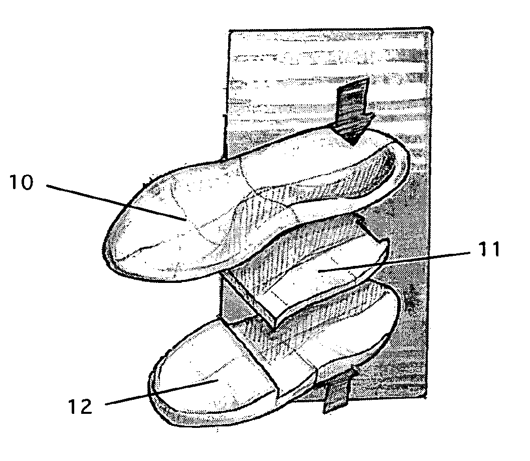
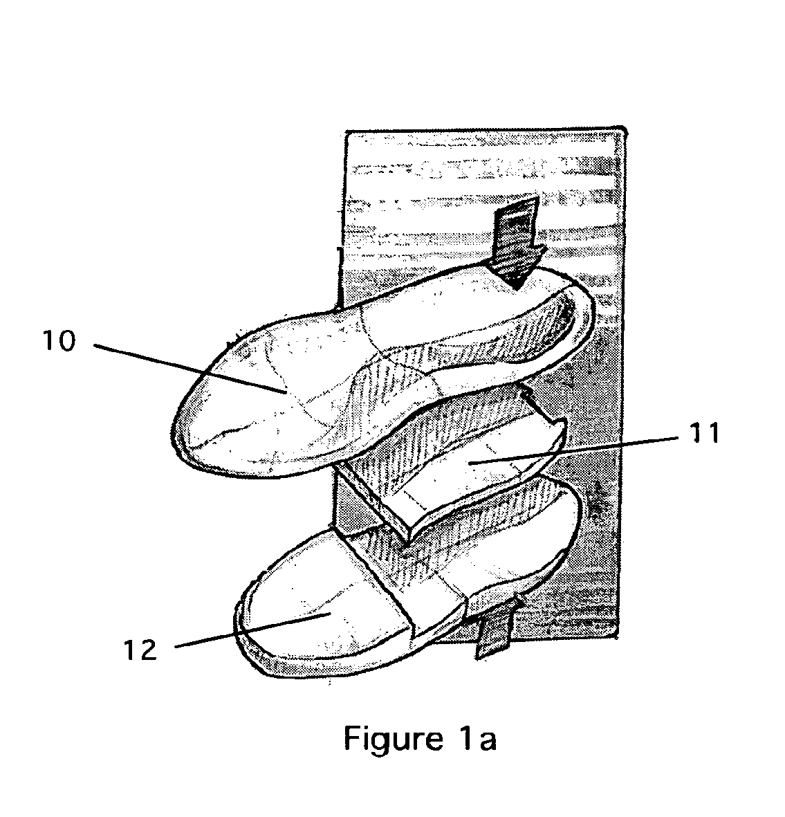
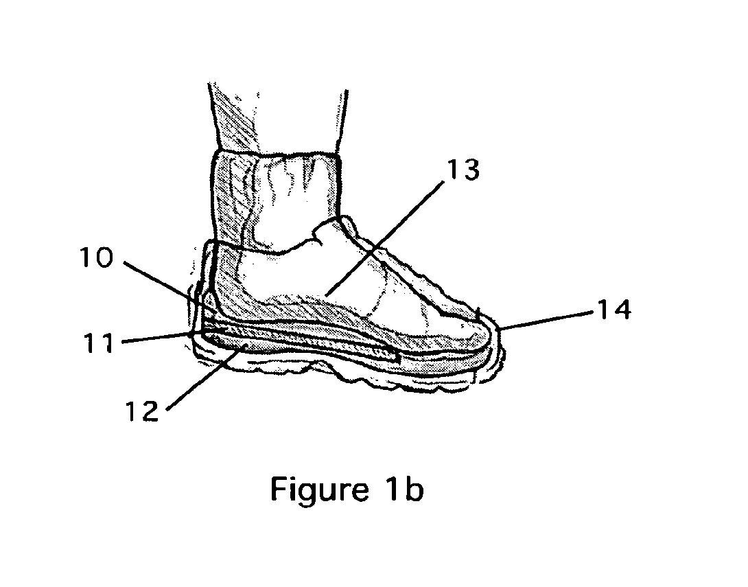
[0083]With reference now the drawings, FIGS. 1a-1c illustrate a wearable system of the present invention in the form of a shoe insole insert. FIG. 1a depicts an exploded view of the insole insert device that is constructed of several layers. The top layer 10 of the insole is a conformable flexible layer which provides a comfortable interface between the foot and actuator components. This top layer 10 has typical foot contours and variations in thickness found on traditional insoles. It typically is made of foam, cloth, or gels. The intermediate layer 11 is an enclosure containing a rechargeable battery source and a control pod with signal generation circuitry, which are not shown for the purpose of clarity and simplification of the drawing. Details of the battery, control pod, and signal generation circuitry will become more apparent with the teachings of this and other embodiments of the present invention.

[0084]A bottom layer 12 shown in FIG. 1a is comprised of a material that can ...

second embodiment

[0092]FIGS. 2a and 2b depict the present invention. FIG. 2a illustrates an insole device including a disposable flexible pad 21 packaged in a disposable pouch 20. The device comprises of an insole pad 21 that is constructed of a thin conformable flexible layer containing thereon several electrode sites 23. A plurality of stimulation electrodes is incorporated in the electrode sites 23 on the top side of the pad facing the bottom of the foot. Stimulation electrodes may include, for example, disposable electrodes, re-useable electrodes to be used with conductive gel, or a new novel electrode design known as a stick-slip electrode system, which will be described in greater detail below.

[0093]These plurality of stimulation electrodes are coupled to a controller housed in a housing 22. Housing 22 also includes a power source, a signal generator, and a controller controlling the signal generator. The controller may also include user interface controls. This controller produces a nondeterm...

third embodiment

[0096]FIGS. 3a and 3b depict the present invention. FIG. 3a illustrates a stimulating device that comprises an ankle cuff 30 connected via a connector assembly 32 to a stimulating layer 31. Stimulating layer 31 is a platform for carrying stimulation electrodes and / or active vibrational actuators for applying stimulation to the plantar surface of the foot 13. Ankle cuff 30 houses electronic components connected to the stimulation electrodes and / or active vibrational actuators providing electrical or mechanical stimulation, respectively. The ankle cuff is wrapped around the ankle and its position is maintained by a fastening device 33, such as a hook-and-eye, Velcro strips, or a clasp, for example, while in use.

[0097]FIG. 3b depicts an expanded view of the ankle cuff of FIG. 3a. The material of the cuff is preferably soft and conformable and contains pockets 34 for batteries and controlling electronics circuitry. The ankle cuff 30 may also include stimulation electrodes or vibrational...


PUM


Abstract

A method and wearable system and for enhancing human balance and gait and preventing foot injury through neurological stimulation of the foot and the ankle. Subthreshold stimulation for neurosensory enhancement is provided via electrodes or vibrational actuators, or combination thereof, disposed in or on a wearable a platform, such as an insole, sock shoe, removable shoe insert, or applied without the support of a platform, to the skin surface of an individual. Suprathreshold stimulation for therapeutic purposes, such as improving blood flow, is also provided by the vibrational actuators. The actuators and electrodes are driven by bias signals generated by a bias signal generator that is coupled to a controller. The signal generator under the control of the controller is adapted to generate a non-deterministic random signal, a repetitive pattern or series of patterns. The controller optionally includes a communication port for interfacing with an external computer for purposes of optimizing and programming the controller. The wearable system is powered by a power source.

Description

RELATED APPLICATION DATA[0001]This application is a non-provisional application of U.S. provisional patent application No. 60 / 452,044 filed Mar. 6, 2003.[0002]This invention was made with Government support under grants (AG08812, AG04390, DK60295, HD40035, and HD37880) awarded by the National Institutes of Health. The Government has certain rights in the invention.BACKGROUND OF THE INVENTION[0003]1. Field of the Invention[0004]The invention relates to improving human balance and gait and preventing foot injury through neurological stimulation of the foot and ankle and more particularly to a wearable platform that provides neurological stimulation to the foot and ankle and to a system for optimizing neurological stimulation.[0005]2. Description of Related Art[0006]Various devices are available for foot support and injury prevention. For example, passive orthoses and braces are described in the art (e.g. U.S. Pat. No. 6,692,454 to Townsend et al. and U.S. Pat. No. 6,676,618 to Anderse...

Claims


Application Information

Patent Timeline
Patent Type & Authority Applications(United States)
IPC IPC(8): A61H1/00A43B3/35A43B7/00A43B13/00A43B17/00A43B19/00A61F5/01A61F5/14A61H39/00A61N1/04A61N1/20A61N1/32A61N2/06
CPCA43B3/0005A61H1/00A43B7/1465A43B13/00A43B17/00A43B19/00A61F5/0111A61F5/14A61H39/002A61H2205/125A61N1/0456A61N1/0468A61N1/0476A61N1/0484A61N1/0492A61N1/20A61N1/32A61N2/06A43B7/00A43B7/1464A43B3/34A61N1/36003A61N1/3603A61H23/02A43B7/146A61H39/007A61N5/0625A61F7/007A61H2201/165A61H2201/169A61H2201/50A61N2005/0659
Inventor HARRY, JASON D.COLLINS, JAMES J.NIEMI, JAMES B.PRIPLATA, ATILLA A.KLESHINSKI, STEPHEN J.
Owner TRUSTEES OF BOSTON UNIV
Why Eureka
Try Eureka