
Load port apparatus and method of detecting object to be processed

a technology of loading port and processing method, which is applied in the field of front-opening interface mechanical standard) system or a load port apparatus, can solve the problems of increasing the time taken by the process, difficult to simply synchronize, and difficulty in achieving both enhancement of operation accuracy to prevent the contact with the inner wall and reduction of operation time. the effect of operation speed and sensor operation speed

Active Publication Date: 2013-03-28
TDK CORPARATION
View PDF2 Cites 5 Cited by
  • Summary
  • Abstract
  • Description
  • Claims
  • Application Information

AI Technical Summary

Benefits of technology

The present invention relates to a load port apparatus for processing objects, such as wafers, in a pod. The apparatus includes a mapping frame that supports a sensor for detecting the presence or absence of objects in the pod. The mapping frame is designed to open and close the pod's lid, and it is driven in two directions to form an angle with the sensor. This angle prevents interference between the sensor and the inner wall of the pod, allowing for faster and easier insertion of the sensor into the pod. The method of detecting objects also increases the speed of the sensor's operation.

Problems solved by technology

This might lead to an increase in the time taken by the process.
In the case where the sensor is driven by a cylinder for operations of the sensor such as upward, downward, advancing and retracting motions, it is difficult to simply synchronize these operations, and it is accordingly difficult to achieve both enhancement in the operation accuracy to prevent the contact with the inner wall and reduction in the operation time.

Method used


Image

  • Load port apparatus and method of detecting object to be processed
  • Load port apparatus and method of detecting object to be processed
  • Load port apparatus and method of detecting object to be processed

Examples


Embodiment Construction

[0024]A preferred embodiment of the present invention will now be described in detail in accordance with the accompanying drawings.

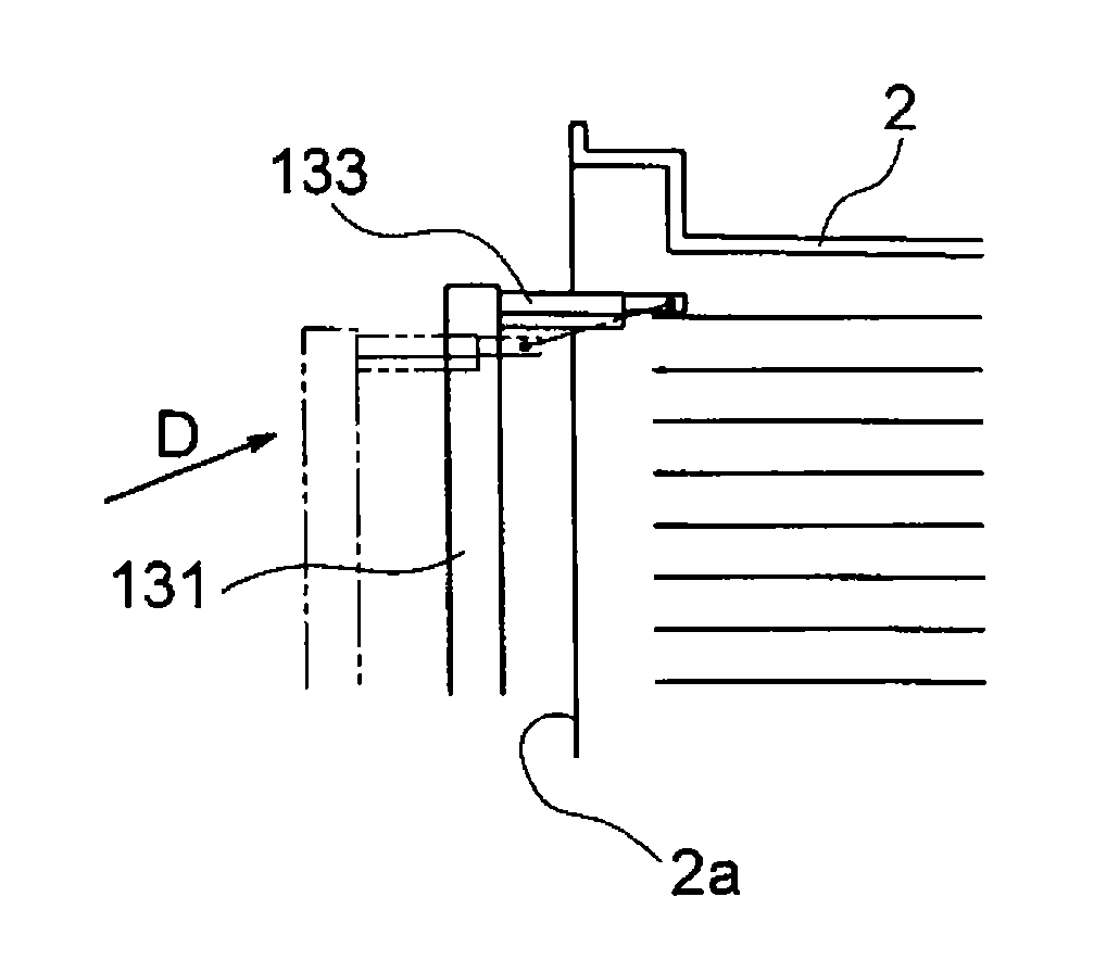
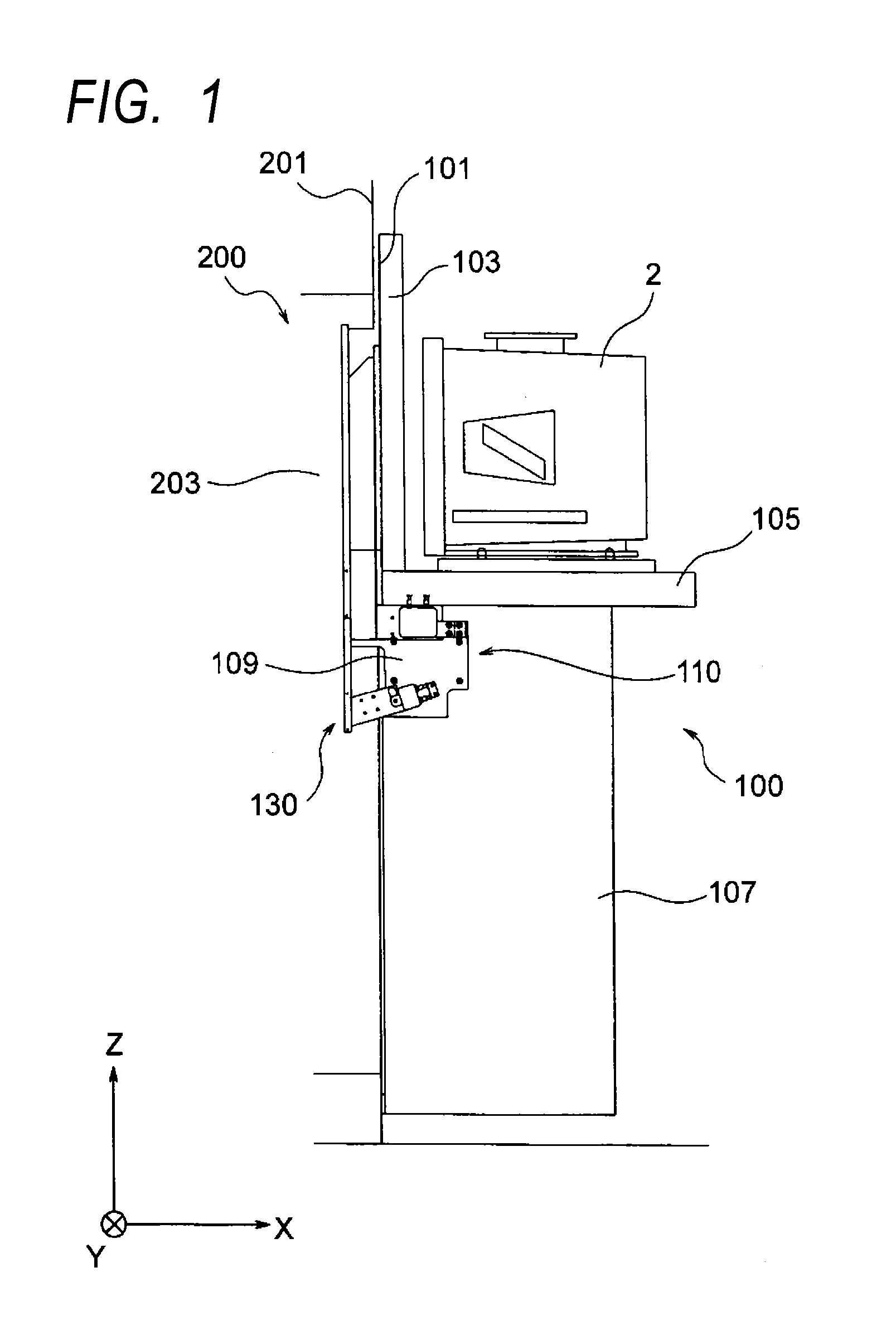
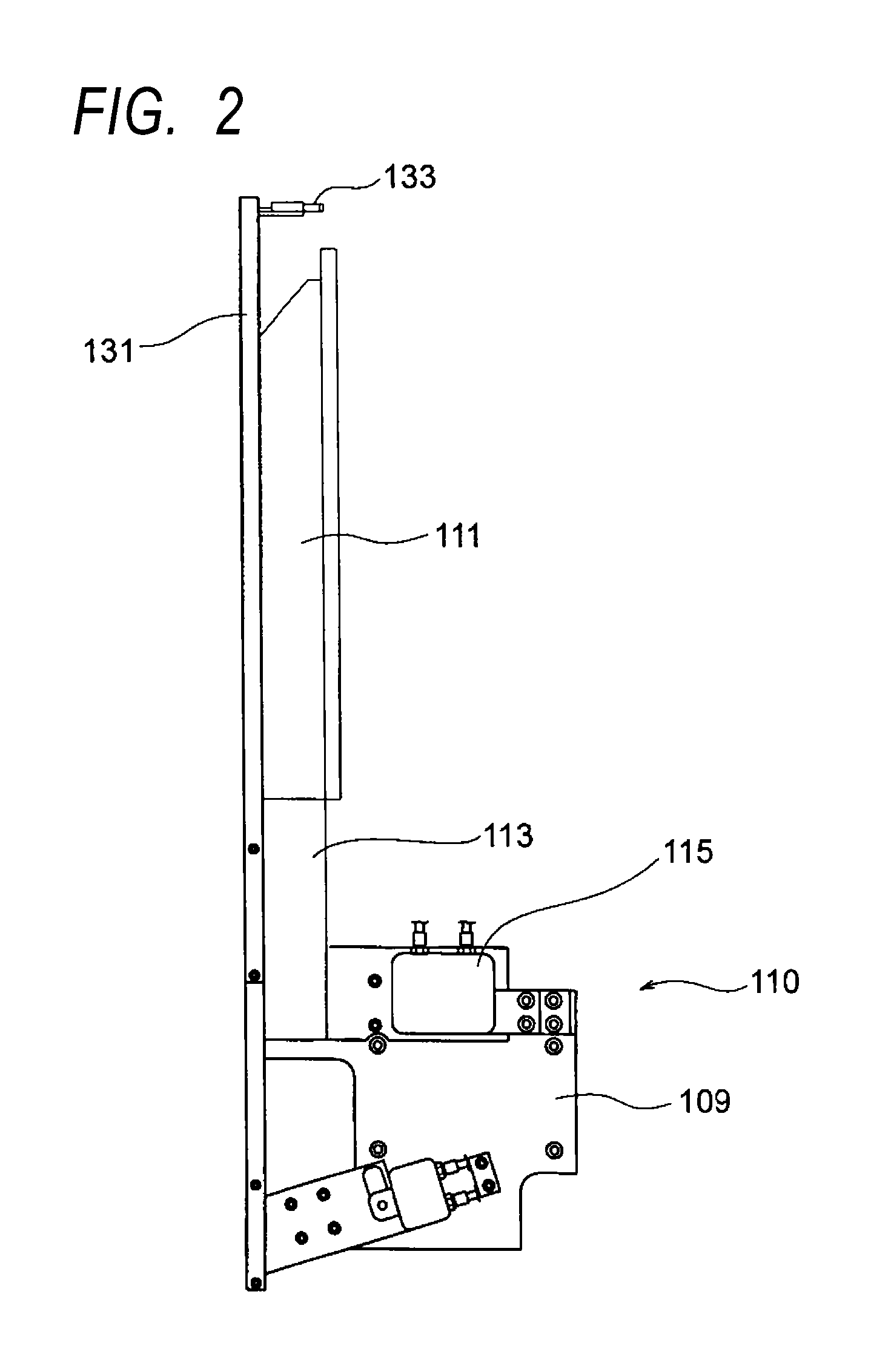
[0025]FIG. 1 is diagram showing the basic construction of a load port apparatus according to an embodiment of the present invention seen from the side with a pods 2 placed on a support table. FIG. 2 is a diagram showing some components in the apparatus shown in FIG. 1 including a door, a mapping frame, a mapping sensor, and a door driving mechanism that drives them. FIG. 3 is a diagram showing objects to be processed shown in FIG. 2 seen from the side other than the pod table side. FIG. 4 is a further enlarged side view showing the door driving mechanism and the frame driving unit shown in FIG. 2. The load port apparatus 100 according to this embodiment has a load port wall 101, an opening periphery cover 103, a support table 105, a lower cover 107, a door unit 110, and a mapping system 130. The X axis in the drawings is taken in the direction in which t...


PUM


Abstract

To enable appropriate wafer mapping in the case where a wafer is stored at the highest level, which is provided as a reserve, of a pod, a load port apparatus drives a mapping frame that supports a sensor by a first driving unit that drives the mapping frame in a first direction parallel to the direction along which wafers in the pod are arranged in an overlapping manner and a second driving unit that drives the mapping frame in a second direction that crosses the first direction in such a way as to form an acute angle in the side in which the sensor starts the mapping.

Description

BACKGROUND OF THE INVENTION[0001]1. Field of the Invention[0002]The present invention relates to what is called a FIMS (Front-Opening Interface Mechanical Standard) system or a load port apparatus, which is used when wafers (which are objects to be processed) stored in the interior of an airtight transfer container called a pod are transferred between semiconductor processing apparatuses in a semiconductor manufacturing process etc. More specifically, the present invention relates to a load port apparatus characterized in its mapping system for detecting the presence / absence of wafers in the interior of a pod placed thereon and a what is called mapping method for detecting the presence / absence of objects to be processed such as wafers.[0003]2. Description of the Related Art[0004]A widely used method in semiconductor manufacturing processes is keeping a highly clean condition only in the interior of three spaces including the interior of processing apparatuses, the interior of a pod ...

Claims


Application Information

Patent Timeline
IPC IPC(8): H01L21/67G01N19/00
CPCH01L21/67772H01L21/67265
Inventor SASAKI, MUTSUOIGARASHI, HIROSHIABE, TOMOSHI
Owner TDK CORPARATION
Learn More