Method and apparatus for reduction of pollutants in combustion effluent

a technology of combustion effluent and pollutants, which is applied in the direction of cleaning using liquids, emission prevention, separation processes, etc., can solve the problems of unsuitable and impractical use of water cannons for the delivery of reagents, high cost, and high cost of piping, air or steam, etc., and achieves rapid switching, simple, robust, and cost-effective

Inactive Publication Date: 2013-03-28
POWER & INDAL SERVICES
View PDF5 Cites 2 Cited by
  • Summary
  • Abstract
  • Description
  • Claims
  • Application Information

AI Technical Summary

Benefits of technology

[0018]Also another important feature of the present invention is that the water cannons may be readily switched from an SNCR function to a de-slagging function, switching from a reagent mixture to a de-slagging compound and otherwise remotely controlling the spray pattern and nozzle spray configuration of the selected water cannons.
[0019]Another advantage of the system of the present invention is that the water cannons are positioned at a more accessible lower location in the boiler than sprayers in typical SNCR injection systems. Also, instead of a conventional retractable injection lance that has a set spray pattern and a set elevation, the system of the present invention provides an SNCR injection system wherein one is able to point the water cannon where needed and adjust the spray pattern, and the system can be quickly switched for spraying a de-slagging compound thereby eliminating the need for expensive SNCR injection systems. The end result is a simple, robust, flexible, and cost effective alternative for boiler operators and owners for NOx reduction goals.
[0020]The unique features of the method and apparatus of the present invention as compared to the competing technology suppliers, is fewer but larger injection lances, aiming capability of the lance, integration of the targeting with operation, enhancement with advanced incrementation for furnace effluent gas temperature control, slag deposition reduction, and more effective control of NOx. Potential further enhancement includes the addition of other chemical compounds, such as magnesium hydroxide, ammonia hydroxide, or other chemical compounds, or suspension mixtures based on future research in this area.

Problems solved by technology

The industry previously considered the use of water cannons for the delivery of a reagent as being unsuitable and impractical.
All this equipment added significant cost, piping, air or steam requirements, and many long term maintenance dollars.

Method used


Image

  • Method and apparatus for reduction of pollutants in combustion effluent
  • Method and apparatus for reduction of pollutants in combustion effluent
  • Method and apparatus for reduction of pollutants in combustion effluent

Examples


Embodiment Construction

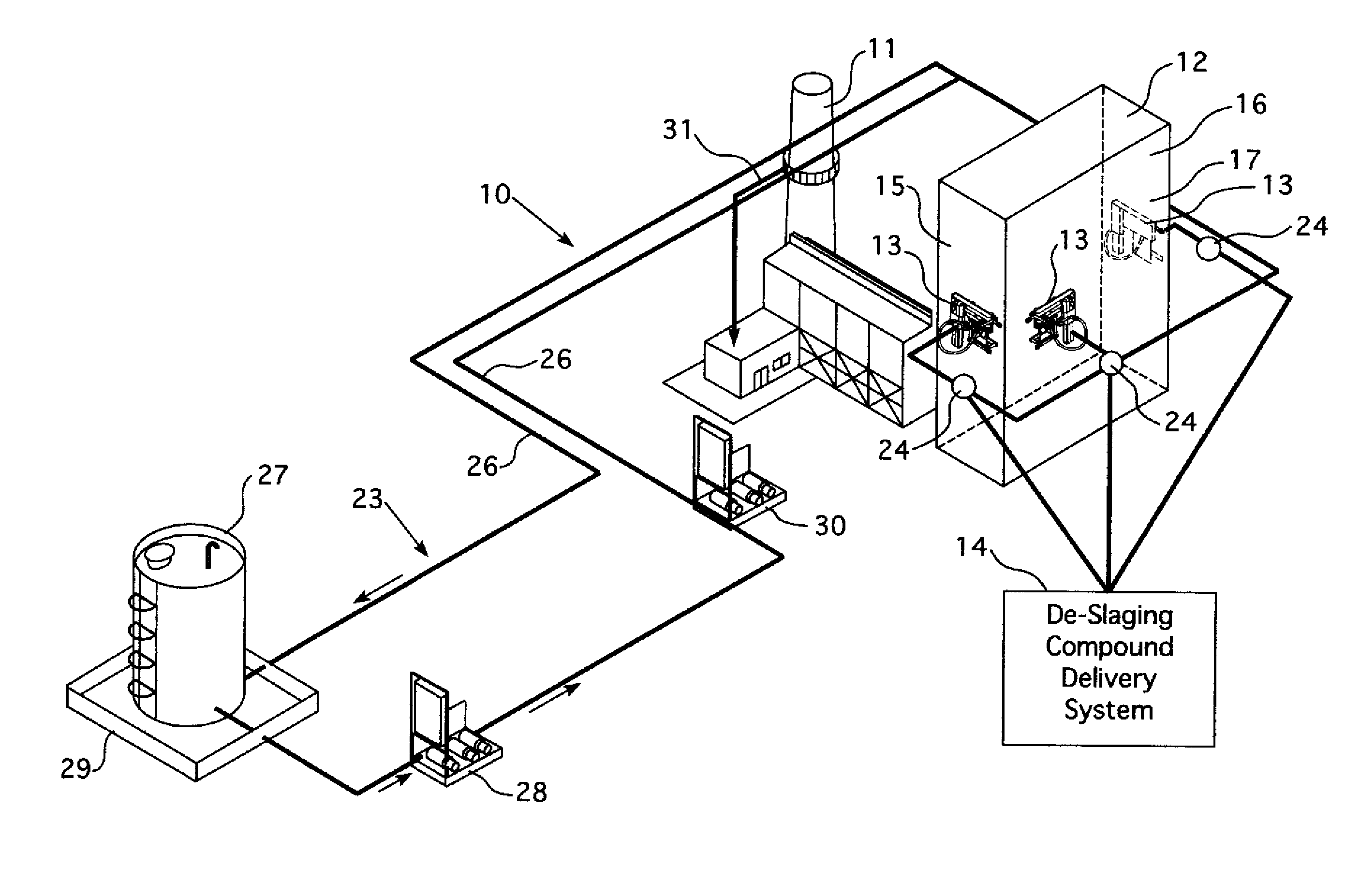
[0024]Referring to the drawings, the apparatus 10 of the present invention is illustrated for selective non-catalytic reduction (SNCR) of pollutant emissions in fossil fuel combustion effluent emanating from stack 11 of fossil fuel combustion furnace 12 having articulatable water cannons 13 installed for removing combustion incrustation in the furnace 12. Water cannons 13 are connected to a source of de-slagging compound from a conventional de-slagging compound delivery system 14 under high pressure for injection by water cannons 13 into furnace 12.

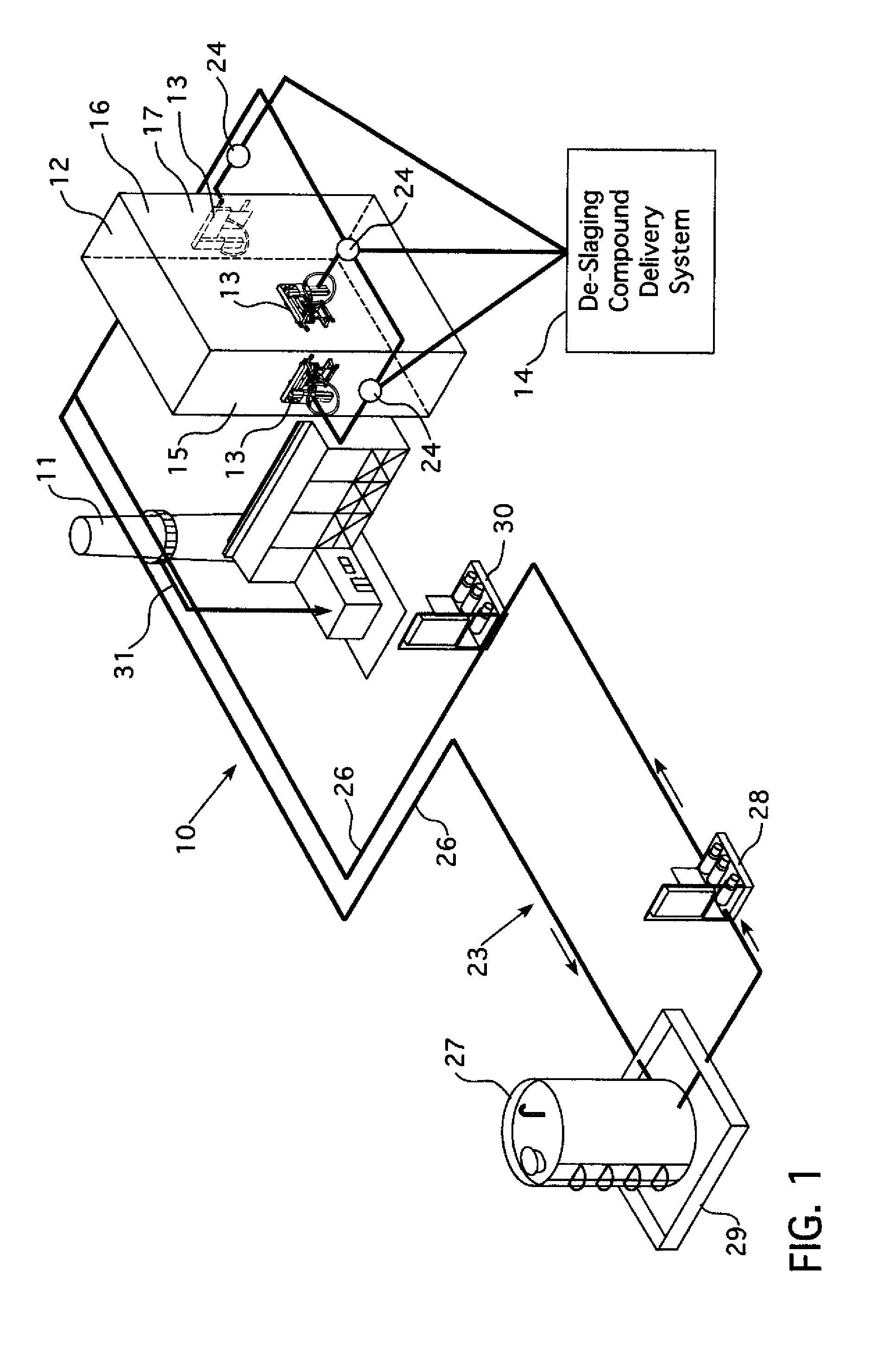
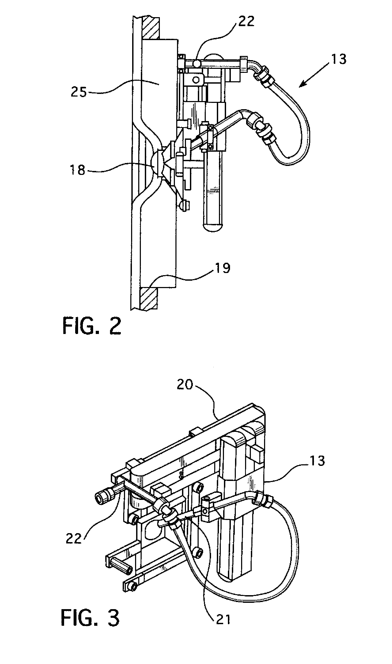
[0025]As is better illustrated in FIGS. 2 and 3, the water cannons 13 in this embodiment are provided in walls 15 and 17 of furnace 12. Each of the water cannons 13 includes an adjustable nozzle 18 positioned within wall box 25 mounted in wall port 19 of furnace 13 in order to project a stream of fluid, such as water with a de-slagging compound, into the interior volume of the furnace 13. Nozzle 18 includes a ball pivot joint as illustrat...


PUM

PropertyMeasurementUnit
velocityaaaaaaaaaa
exit velocityaaaaaaaaaa
velocityaaaaaaaaaa

Abstract

Selective non-catalytic reduction (SNCR) of pollutant remissions in a fossil fuel combustion furnace having water cannons installed therein for removing combustion incrustation is accomplished by using the water cannons intended for de-slagging by mixing a reagent with water and administering the mixture under high velocity and high blast flow rate to the interior of the furnace for reduction of pollutant emissions, such as NOx, with the water cannons. The water cannons may be switched from the SNCR function to a de-slagging function.

Description

CROSS REFERENCE[0001]This patent application claims the benefit of U.S. Provisional Patent Application No. 61 / 626,311, filed 23 Sep. 2011, the contents of which are incorporated herein by reference.BACKGROUND OF THE INVENTION[0002]This invention relates to the reduction of pollutants, such as nitrogen oxide, in combustion effluent of a carbonaceous fuel. More particularly, this invention relates to a process and apparatus to accomplish this.[0003]Selective non-catalytic reduction (SNCR) have been used for many years to reduce the oxides of nitrogen in combustion processes. SNCR has been used for the reduction of NOx to meet regulatory limits by a chemical process in the combustion effluent. This is generally accomplished by the uniform injection of a reagent into the furnace's flue gas combustion stream.[0004]SNCR uses a reagent, either urea or anhydrous ammonia, sprayed directly into the furnace at specified locations to induce a reaction between the reagent and the nitrogen oxide ...

Claims


Application Information

Patent Timeline
Patent Type & Authority Applications(United States)
IPC IPC(8): F23J15/04B08B3/02B08B3/10B01D53/56
CPCB01D53/56B08B3/02F23J15/04B01D53/79B01D2251/2062F23J2219/20B01D2258/0283F23J2215/10F23J7/00F23J3/023B01D2251/2067
Inventor HIGGINS, TERRY
Owner POWER & INDAL SERVICES
Why Eureka
Try Eureka