Muffler for small-sized vehicle

a small-sized vehicle and muffler technology, applied in the direction of engines, mechanical apparatus, machines/engines, etc., to achieve the effect of reducing the resistance of the exhaust gas, preventing the resonance, and reducing the pressure of the exhaust gas

Active Publication Date: 2013-03-28
HONDA MOTOR CO LTD
View PDF5 Cites 13 Cited by
  • Summary
  • Abstract
  • Description
  • Claims
  • Application Information

AI Technical Summary

Benefits of technology

[0015]In other embodiments, the plate thickness of the outer plate of the muffler main body, which corresponds to the upstream-side expansion chamber having the larger volume with the catalyst contained therein, is made equal to the plate thickness of the outer plate of the muffler main body, which corresponds to the downstream-side expansion chambers each having a smaller volume. At the same time, it is possible to prevent the “resonance” of the outer plate which corresponds to the upstream-side expansion chamber having the larger volume. This makes it possible to prevent the muffler as a whole from being constructed in a larger size.
[0016]In addition to the enlargement of the volume of the upstream-side expansion chamber in which the catalyst is contained, in certain embodiments, a long distance from the outlet of the catalyst to the partition wall for partitioning the expansion chamber is secured. Thus, it is possible to reduce the pressure of the exhaust gas and to decrease the exhaust resistance further. Concurrently, it is possible to prevent noise which would otherwise occur due to the “resonance” of the outer plate.
[0017]In other embodiments, the outlet of the catalyst is directed upward, and the face-to-face weld portion of the cylinder-shaped

Problems solved by technology

However, the enlargement of the volume of the expansion chamber containing the catalyst poses a problem that an outer plate of the muffler, which surround

Method used


Image

  • Muffler for small-sized vehicle
  • Muffler for small-sized vehicle
  • Muffler for small-sized vehicle

Examples


Embodiment Construction

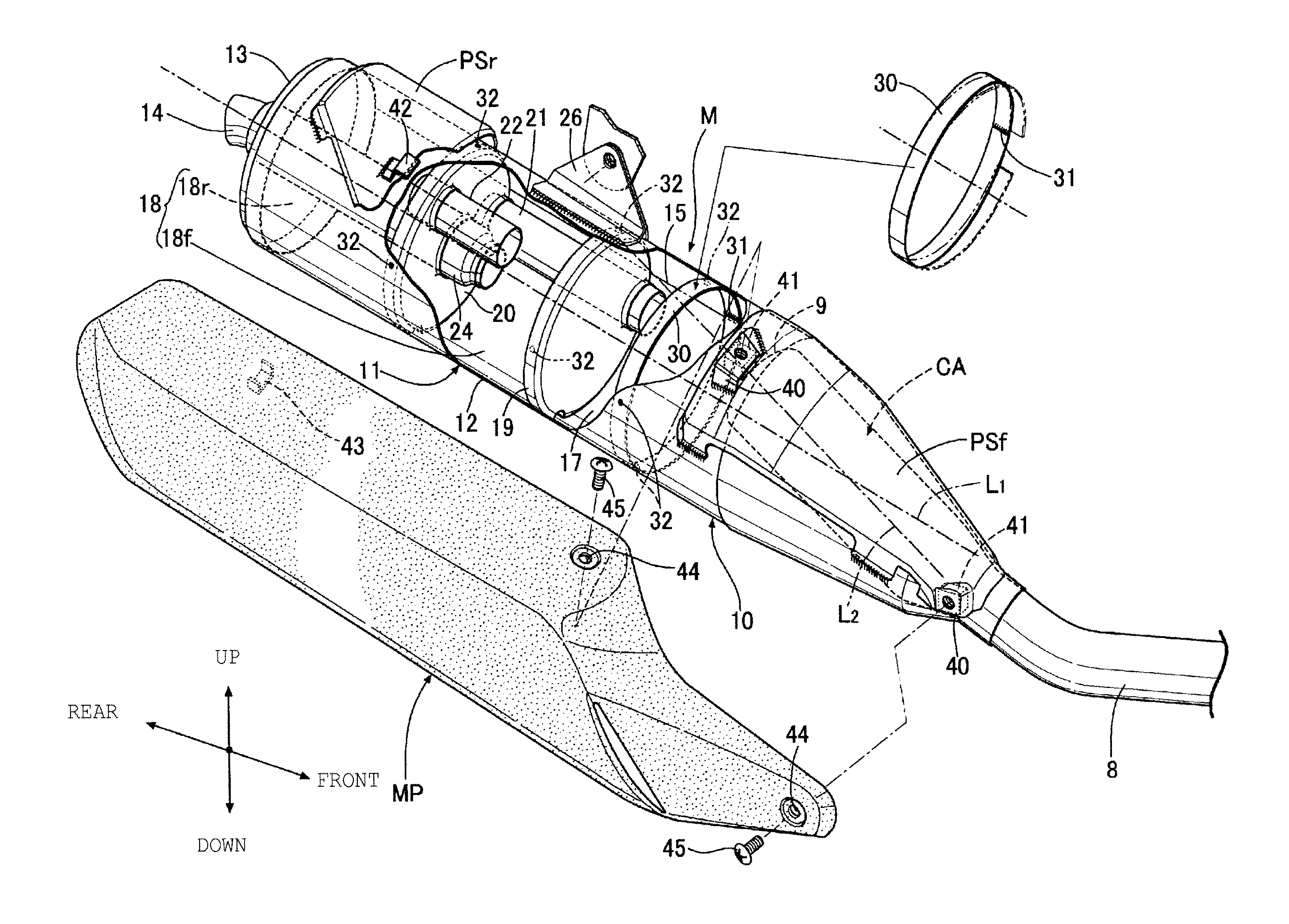
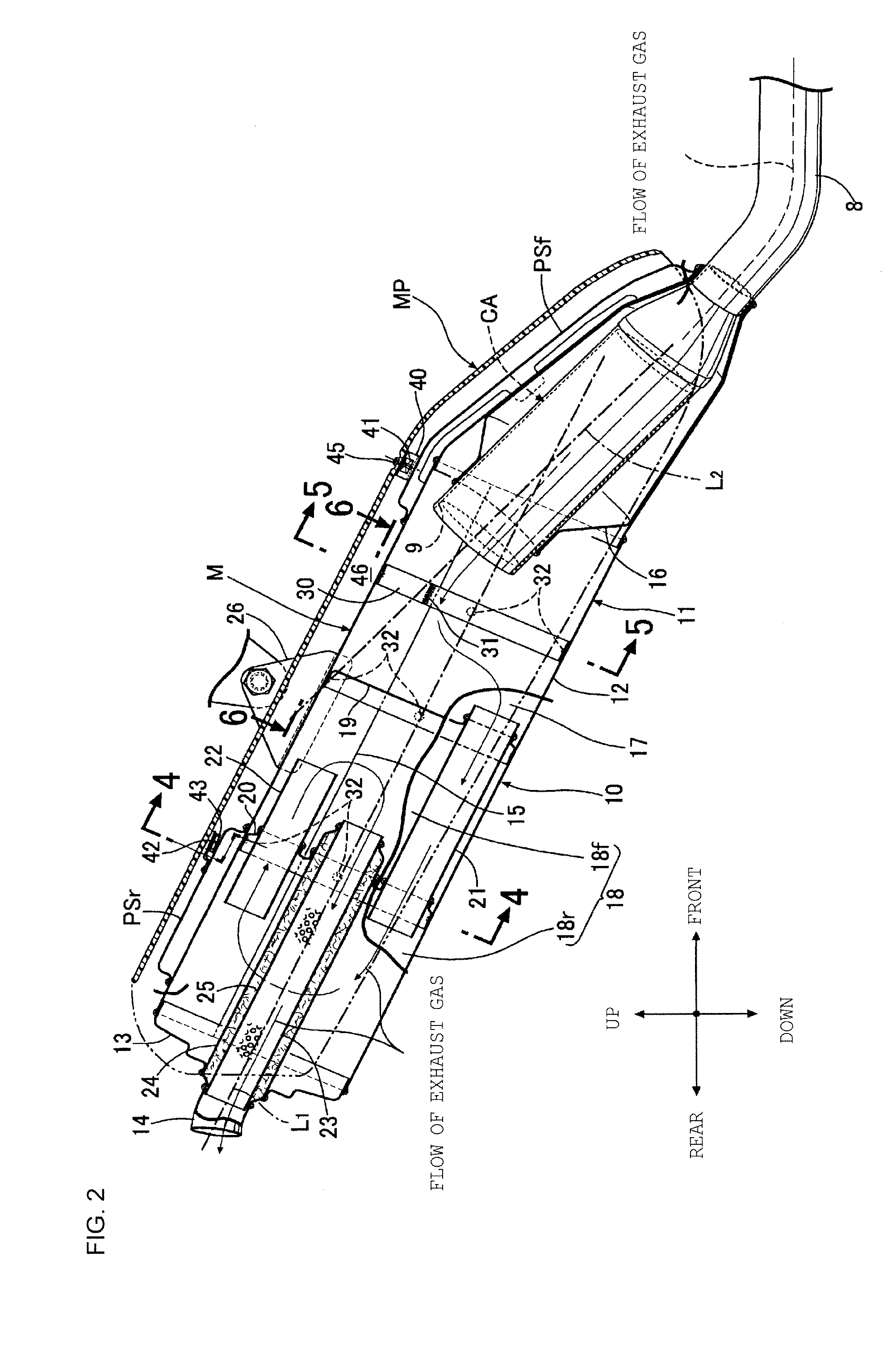
[0028]An embodiment of the present invention will specifically be described below on the basis of the accompanying drawings.

[0029]Front, rear, left, right, upper, and lower remarks in the descriptions of the following embodiment are based on a traveling direction of a motorcycle on which an exhaust system Ex is mounted.

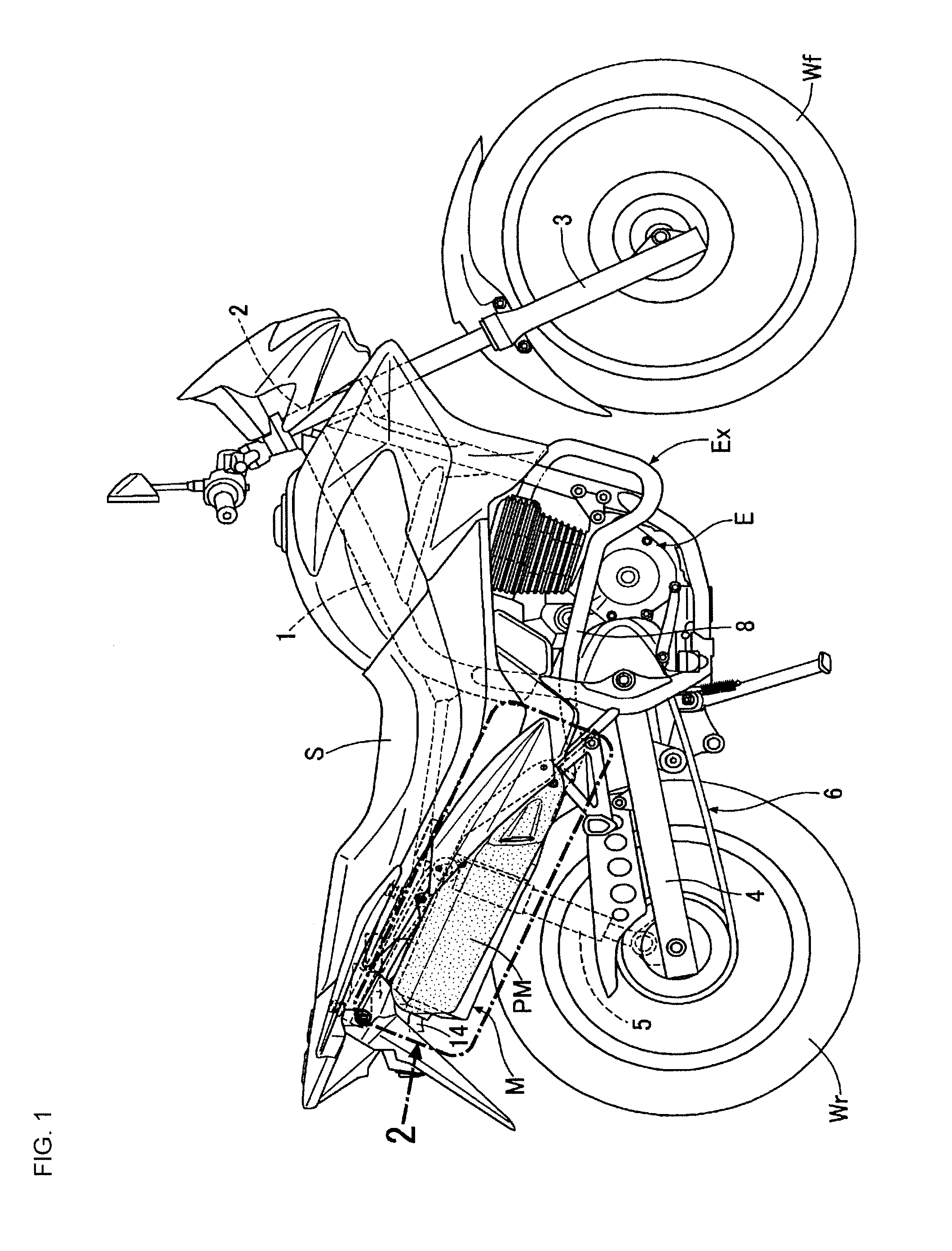
[0030]This embodiment represents a case where a muffler for a smaller-sized vehicle of the present invention is carried out as the exhaust system Ex mounted on the motorcycle.

[0031]FIG. 1 shows a saddle riding-type motorcycle which includes the muffler for a small-sized vehicle of the present invention. A head pipe 2 is provided at a front-end portion of a vehicle body frame 1 formed from pipe members and the like. A front wheel Wf is suspended on front forks 3 which are steerably supported by this head pipe 2. A swingarm 4, on which a rear wheel Wr is suspended, is mounted on a pivot in the rear portion of the vehicle body frame 1 in a vertically swingable manner. Th...


PUM


Abstract

The inside of a muffler main body formed from an outer plate into the shape of a cylinder is divided into an upstream-side expansion chamber and downstream-side expansion chambers by partition walls. A catalyst is contained in the upstream-side expansion chamber having a larger volume, and a cylinder-shaped reinforcement member is attached to an inner surface of the outer plate of the upstream-side expansion chamber.

Description

BACKGROUND[0001]1. Field[0002]The present invention relates to a muffler for a small-sized vehicle, in which the muffler is connected to an exhaust system of an engine of a small-sized vehicle such as a motorcycle, a catalyst is contained in the muffler, and a reduction in exhaust resistance and a decrease in exhaust noise are achieved at the same time.[0003]2. Description of Related Art[0004]A conventional muffler has been known in which the inside of a cylinder-shaped case of the muffler is divided into multiple expansion chambers by partition walls, and a catalyst is contained in a particular one of the expansion chambers (see Patent Document 1, Japanese Patent Application Publication No. 2005-240720).[0005]In such a muffler, by enlarging the volume of the expansion chamber containing the catalyst this expansion chamber is expected to make the exhaust pressure lower at the downstream of the catalyst, to reduce the exhaust resistance, to make the flow of the exhaust gas better, to...

Claims


Application Information

Patent Timeline
IPC IPC(8): F01N13/08
CPCF01N3/2885Y02A50/20
Inventor HAYAMA, YOSHITAKANAKAMURA, KENICHIRO
Owner HONDA MOTOR CO LTD
Why Eureka
Try Eureka