Rear-mounted retractable aerodynamic structure for cargo bodies

an aerodynamic structure and cargo technology, applied in the direction of roofs, transportation and packaging, vehicle arrangements, etc., can solve the problems of aerodynamic structures that swing upwards require substantial strength or force to be moved away from the doors, and most attempts to provide aerodynamic structures that integrate with the structure and function of the rear cargo doors of trucks have been unsuccessful and/or impractical to use and operate,

Inactive Publication Date: 2013-03-28
STEMCO LP
View PDF2 Cites 88 Cited by
  • Summary
  • Abstract
  • Description
  • Claims
  • Application Information

AI Technical Summary

Benefits of technology

[0008]This invention overcomes the disadvantages with respect to aerodynamic structures for the rear and cargo bodies with rolling cargo doors. A rear fairing device (illustratively) for a rolling door trailer is retractable to allow for contact with loading bays. The various embodiments of the invention allow for full access to the loading door of a rolling door trailer. The aerodynamic structure includes a nacelle and corresponding winglet constructed and arranged such that the winglet provides aerodynamic drag reduction and is retractable when an amount of force i...

Problems solved by technology

The flat, projecting front face of a cargo body is a substantial source of drag, above the cab roof.
Nevertheless, most attempts to provide aerodynamic structures that integrate with the structure and function of the rear cargo doors of a truck have been unsuccessful and/or impractical to use and operate.
Such rear aerodynamic structures are typically large and difficult to remove from the rear so as to access the cargo doors when needed.
However, aerodynamic structures that swing upwardly require substantial strength or force to be moved away from the doors, and also require substantial height clearance above an already tall cargo body.
While this requires less force to move, it also requires substantial side clearance—w...

Method used


Image

  • Rear-mounted retractable aerodynamic structure for cargo bodies
  • Rear-mounted retractable aerodynamic structure for cargo bodies
  • Rear-mounted retractable aerodynamic structure for cargo bodies

Examples


Embodiment Construction

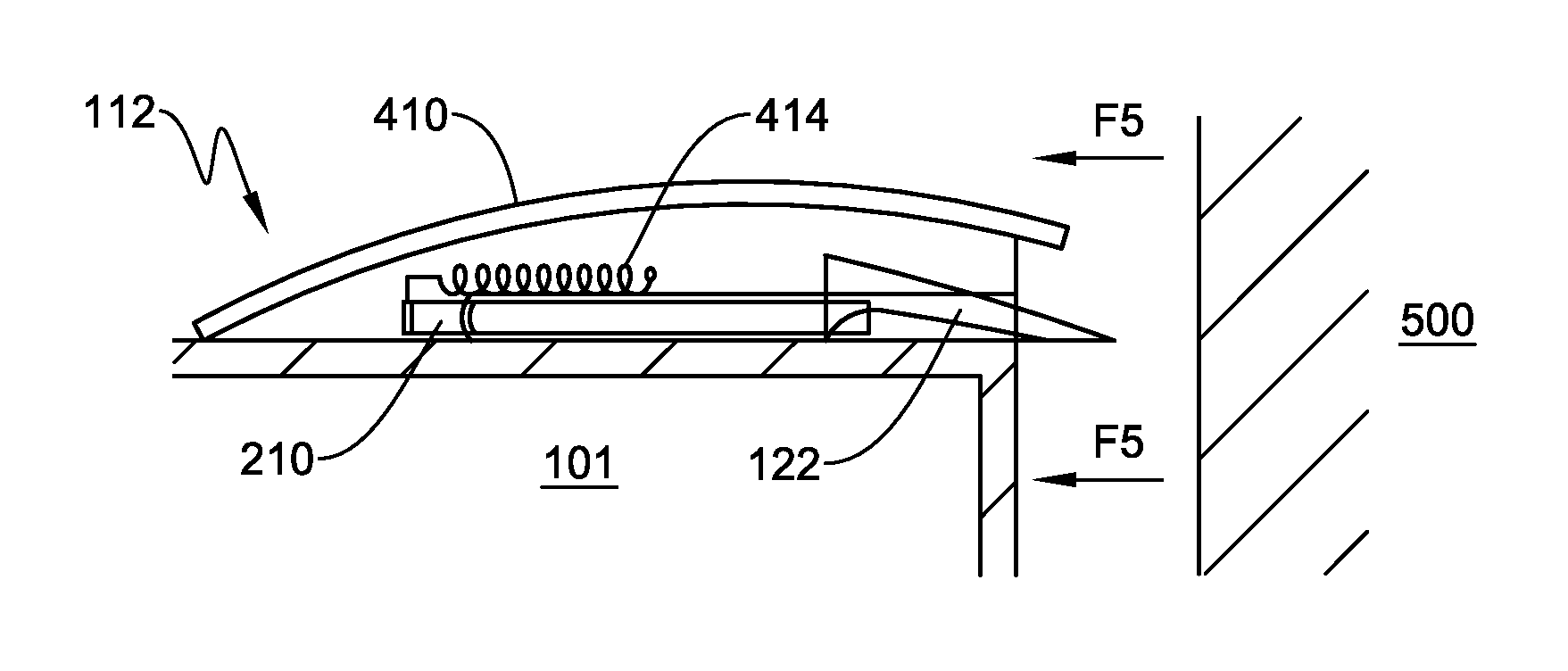
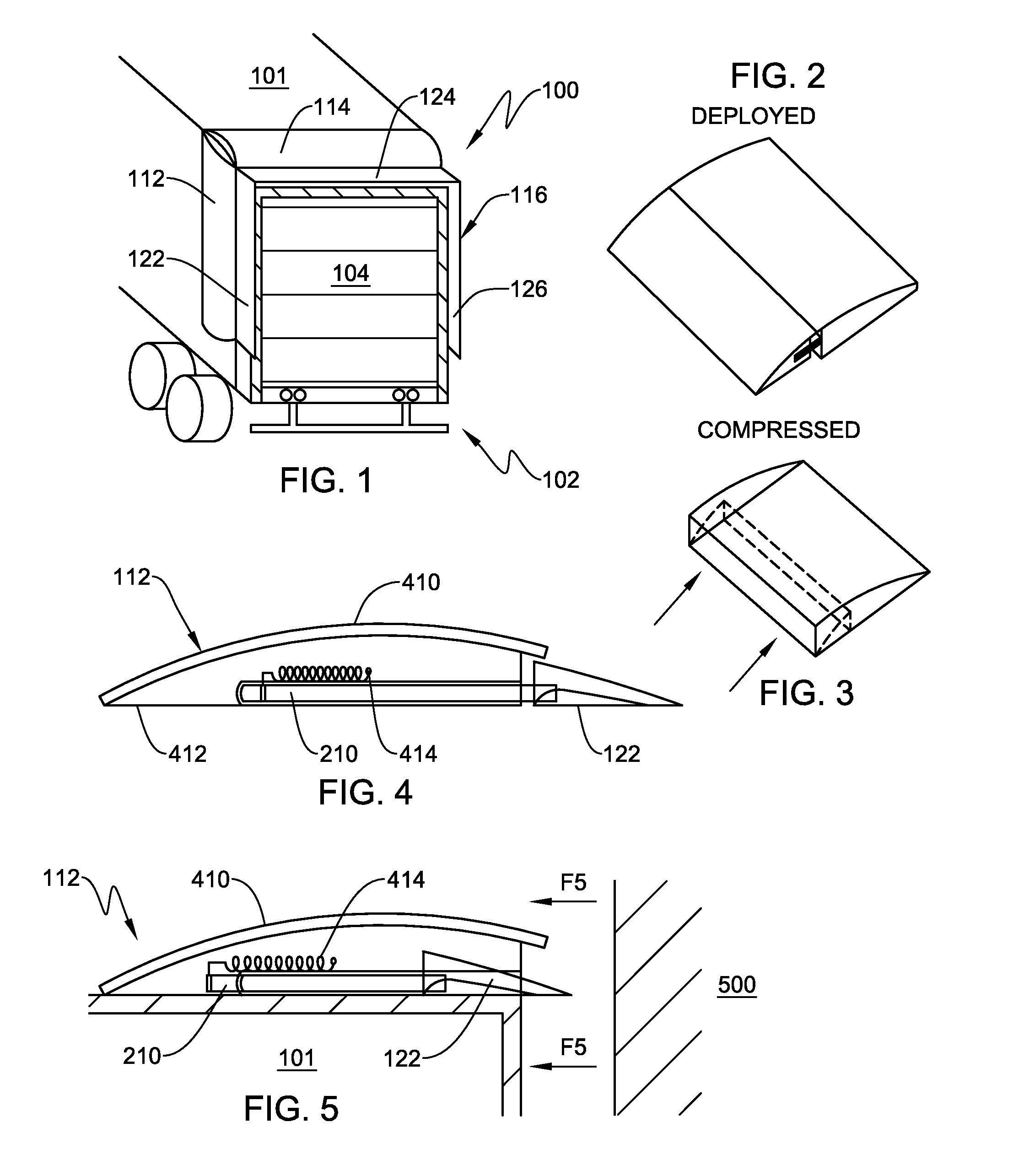
[0115]In an illustrative embodiment, a rear-mounted retractable aerodynamic structure includes a nacelle on at least a portion of the top and / or sides of a cargo body. The nacelle can comprise a unitary structure or a plurality of compartments or segments that together comprise a cavity to improve the aerodynamic drag of the cargo body. This and other components herein can be constructed from any acceptable material that can be formed into the described surfaces including polymer sheets, composite and sheet metal. The nacelle includes at least one retractable winglet to improve airflow, and is constructed and arranged to retract when a predetermined amount of force is exerted on the winglet. Accordingly, for example, when the truck is backing up to a loading area, the winglet retracts into the nacelle to provide the needed clearance for full access to the cargo body.

[0116]Reference is now made to FIG. 1 showing a rear view of a retractable aerodynamic structure 100 mounted on a carg...


PUM


Abstract

An aerodynamic structure attached to the sides and top of a truck cargo body (either a stand-alone trailer or a “straight truck” with the cab and cargo area as a fixed vehicle) at the aftmost region, which rear typically contains a rolling door assembly, which rolls upwardly. An aerodynamic structure is permanently attached to the sides and top of the trailer in a manner that extend past the aftmost plane of the truck cargo body and retract to the aftmost plane of the truck cargo body when subjected to a force, allowing this device to be backed into structures. The retracted orientation allows for the rear of the trailer to be fully accessible for loading and unloading, and does not reduce the size of the opening of the trailer. The various embodiments of the invention allow for automated deployment once the force used to compress the structure is removed.

Description

RELATED APPLICATIONS[0001]This application claims the benefit of U.S. Provisional Application Ser. No. 61 / 537,047, filed Sep. 20, 2011, entitled REAR-MOUNTED RETRACTABLE AERODYNAMIC STRUCTURE FOR CARGO BODIES, the entire disclosure of which is herein incorporated by reference. This application also claims the benefit of U.S. Provisional Application Ser. No. 61 / 577,923, filed Dec. 20, 2011, entitled REAR-MOUNTED RETRACTABLE AERODYNAMIC STRUCTURE FOR CARGO BODIES, the entire disclosure of which is herein incorporated by reference. This application also claims the benefit of U.S. Provisional Application Ser. No. 61 / 600,579, filed Feb. 17, 2012, entitled REAR-MOUNTED RETRACTABLE AERODYNAMIC STRUCTURE FOR CARGO BODIES, the entire disclosure of which is herein incorporated by reference.FIELD OF THE INVENTION[0002]The present invention relates to rear-mounted aerodynamic structures for cargo bodies having rolling rear access doors.BACKGROUND OF THE INVENTION[0003]Trucking is the primary mo...

Claims


Application Information

Patent Timeline
IPC IPC(8): B62D35/00
CPCB62D35/007B62D35/001Y02T10/82
Inventor SMITH, ANDREW F.DICKINSON, BARRIE J.GROSSMANN, JEFFREY J.CHOLNOKY, ROBERT R.NIEMIEC, JARED A.POLIDORI, MICHAEL W.
Owner STEMCO LP
Why Eureka
Try Eureka