Ion Sensing Method for Capacitive Discharge Ignition

Active Publication Date: 2013-03-28
ALTRONIC
View PDF8 Cites 4 Cited by
  • Summary
  • Abstract
  • Description
  • Claims
  • Application Information

AI Technical Summary

Benefits of technology

This patent describes a method for ion sensing in a CD ignition system for an internal combustion engine. The method involves initializing the system to transfer energy to the ignition coil to cause a spark breakdown across the spark plug, then repeatedly opening and closing a controllable switch to achieve the desired bias voltage across the spark plug electrodes. The system is also equipped with an electronic circuit to control the switch and a spark plug with electrodes in series with the secondary winding of the ion sensing transformer, allowing for the observation of current in the secondary winding circuit to confirm ionization in the vicinity of the spark plug electrodes. The technical effect of this patent is to provide a reliable and accurate method for ion sensing in a CD ignition system for an internal combustion engine, for improving engine performance and efficiency.

Problems solved by technology

Misfire is the failure of the ignition to ignite the air / fuel mixture near the end of the compression stroke resulting in loss of power.
Knocking is vibrations created in the cylinder, often the result of early ignition during the compression stroke.
In such systems there can be little if any adjustment of the biasing voltage which is stored during the initial sparking.

Method used


Image

  • Ion Sensing Method for Capacitive Discharge Ignition
  • Ion Sensing Method for Capacitive Discharge Ignition
  • Ion Sensing Method for Capacitive Discharge Ignition

Examples


second embodiment

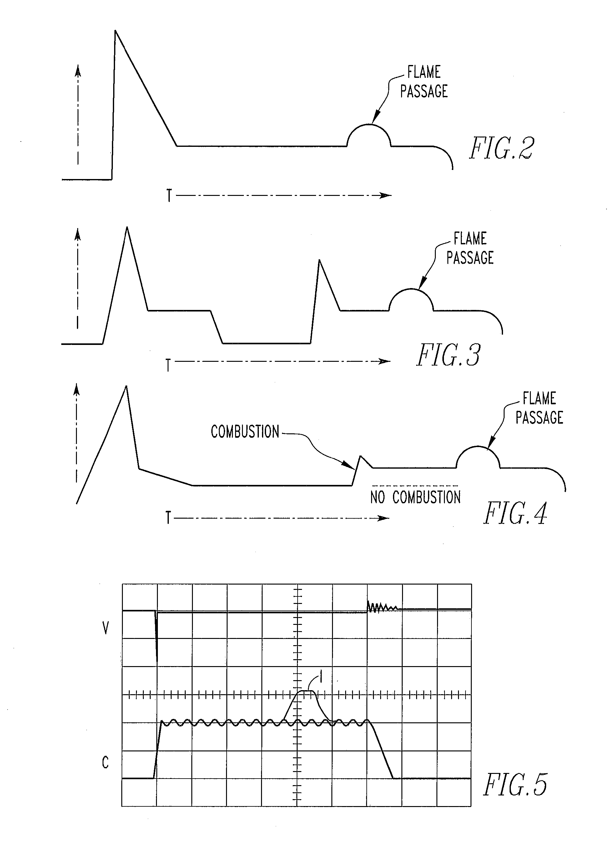
[0032]Referring to FIG. 3, according to this invention, after the initial closing period of the controllable switch to cause a spark breakdown and a period of time closing the controllable switch to implement a second spark breakdown, then maintaining a low voltage bias across the spark plug electrodes by controlling the ratio of opening and closing periods for a time sufficient to detect passage of the flame front between the spark plug electrodes.

third embodiment

[0033]Referring to FIG. 4, according to this invention, after the initial closing period of the controllable switch to cause a spark breakdown, a low voltage bias across the spark plug electrodes is maintained by controlling the ratio of opening and closing periods to cause a second spark breakdown only if the initial spark breakdown caused continuous combustion of the air / fuel mixture and then maintaining a low voltage bias across the spark plug electrodes by controlling the ratio of opening and closing periods for a time sufficient to detect passage of the flame front between the spark plug electrodes.

fourth embodiment

[0034]According to the invention, the total secondary current (spark plus ion current) which is established after the spark breakdown event is maintained at a virtually constant value for a fixed time long enough for the ion current to be sensed, by controlling the ratio of the opening and closing periods of the primary switch. The total current consisting of the spark current plus the ion current would normally decline rapidly after the spark breakdown thus forming a waveform which is triangular in shape. By forcing the total current value to be held to a constant value, the total current waveform will be rectangular in shape for the fixed constant current time period. In this embodiment, the higher the ion current present during this period of time, the less energy the primary drive circuit will need to provide to maintain this constant value of total current. The ratio of the opening and closing periods of the primary switch can then be used to determine the relative ion concentr...


PUM


Abstract

A method of ion sensing in a CD ignition system for an internal combustion engine comprises: a) closing the controllable switch in synchronism with the internal combustion engine for a period of time to transfer energy to the ignition coil primary to cause a spark breakdown across the spark plug; and b) observing the current in the secondary winding circuit indicative of ionization in the vicinity of the spark plug electrodes.

Description

BACKGROUND OF THE INVENTION[0001]1. Field of the Invention[0002]This invention relates to a method of ion sensing for capacitive discharge ignitions for internal combustion engines and, in one embodiment, using pulse width modulation for biasing the secondary winding circuit during the sensing period.[0003]2. Description of Related Art[0004]Ion sensing or, more accurately ionization current sensing, is a technique for determining conditions within the cylinder of an internal combustion engine including, for example, misfire, knocking, and peak pressure. Misfire is the failure of the ignition to ignite the air / fuel mixture near the end of the compression stroke resulting in loss of power. Knocking is vibrations created in the cylinder, often the result of early ignition during the compression stroke. Peak pressure is the greatest pressure in the cylinder which optimally occurs near the top of the compression stroke. Ion sensing enables the correction or adjustment of the ignition to ...

Claims


Application Information

Patent Timeline
IPC IPC(8): F02P17/00
CPCF02P3/0846F02P15/08F02P2017/128F02D35/021G01L23/221F02P17/12
Inventor STEINRUECK, PETERRANEGGER, GERHARDLEPLEY, JOSEPH M.PIRKO, STEVEN B.
Owner ALTRONIC
Why Eureka
Try Eureka