Radio communication device and signal division method

a radio communication device and signal division technology, applied in the direction of frequency-division multiplex, orthogonal multiplex, instruments, etc., can solve the problems of worse frequency resource utilization efficiency, and achieve the effect of reducing isi and reducing the loss of orthogonality of a dft matrix

Active Publication Date: 2013-03-28
SUN PATENT TRUST
View PDF4 Cites 32 Cited by
  • Summary
  • Abstract
  • Description
  • Claims
  • Application Information

AI Technical Summary

Benefits of technology

[0018]When dividing an SC-FDMA signal into a plurality of clusters and mapping the plurality of clusters to discontinuous frequency bands (when using C-SC-FDMA), the present invention can reduce ISI caused by the loss of orthogonality of a DFT matrix.

Problems solved by technology

However, when frequency resource allocation is limited as described above, vacancy is produced in uplink shared frequency resources (e.g. PUSCH (Physical Uplink Shared CHannel)) and the efficiency of the use of frequency resources becomes worse.

Method used


Image

  • Radio communication device and signal division method
  • Radio communication device and signal division method
  • Radio communication device and signal division method

Examples


embodiment 1

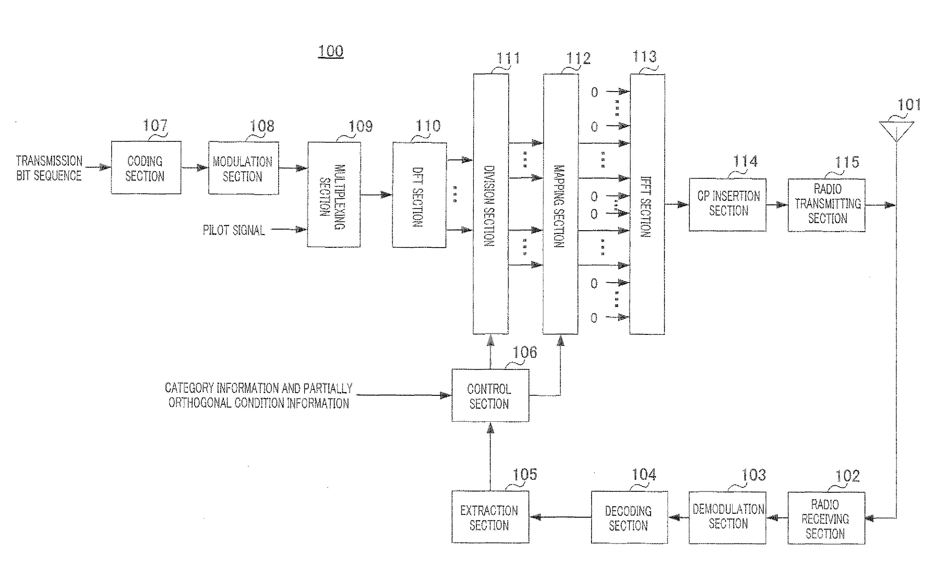
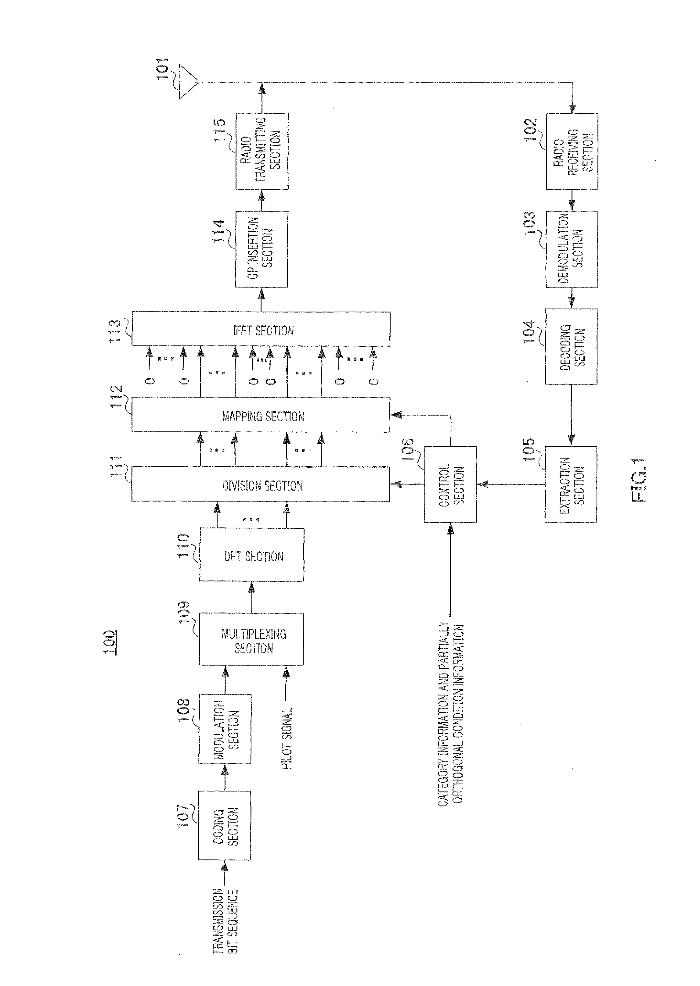
[0058]FIG. 1 shows a configuration of terminal 100 according to the present embodiment.

[0059]In terminal 100, radio receiving section 102 receives a control signal transmitted from a base station (not shown) via antenna 101, applies reception processing such as down-conversion and A / D conversion to the control signal and outputs the control signal subjected to the reception processing to demodulation section 103. This control signal includes frequency resource information showing uplink frequency resources allocated to each terminal and MCS information showing MCS (Modulation and channel Coding Scheme) set in each terminal.

[0060]Demodulation section 103 demodulates the control signal and outputs the demodulated control signal to decoding section 104.

[0061]Decoding section 104 decodes the control signal and outputs the decoded control signal to extraction section 105.

[0062]Extraction section 105 extracts frequency resource information directed to terminal 100 included in the control ...

embodiment 2

[0137]The present embodiment will describe a case where MIMO (Multi-Input Multi-Output) transmission, which is one of transmission techniques for realizing high-speed, large-volume data transmission, is used. The MIMO transmission technique provides a plurality of antennas for both a base station and a terminal, provides a plurality of propagation paths (streams) in a space between radio transmission / reception, spatially multiplexes the respective streams, and can thereby increase throughput.

[0138]This will be described more specifically below. FIG. 9 shows a configuration of terminal 200 according to the present embodiment. Terminal 200 is provided with two antennas (antennas 101-1 and 101-2) that transmit C-SC-FDMA signals (a plurality of clusters) using two streams (stream #1 and stream #2).

[0139]Furthermore, terminal 200 includes C-SC-FDMA processing sections 201-1 and 201-2 made up of coding section 107, modulation section 108, multiplexing section 109, DFT section 110 and divi...

embodiment 3

[0156]A case has been described in Embodiment 2 where when FSTD (Frequency Switched Transmit Diversity) is used, a terminal switches between transmitting antennas for each frequency band (or cluster) having a partially orthogonal bandwidth. Furthermore, in this case, a case has been described where a plurality of clusters are mapped to non-continuous frequency bands when viewed in the frequency domain of all transmitting antennas. By contrast, in the present embodiment, when using FSTD that switches between transmitting antennas for each frequency band (or cluster) having a partially orthogonal bandwidth, a terminal maps a plurality of clusters to continuous frequency bands when viewed in the frequency domain of all transmitting antennas.

[0157]That is, when FSTD is used in Embodiment 2, as shown in FIG. 11, clusters having partially orthogonal bandwidths mapped to the respective antennas are mapped to non-continuous frequency bands and a plurality of clusters are mapped to non-conti...


PUM


Abstract

Provided is a radio communication device which can reduce ISI caused by destruction of an orthogonal DFT matrix even when an SC-FDMA signal is divided into a plurality of clusters and the clusters are respectively mapped to discontinuous frequency bands. The radio communication device includes a DFT unit (110), a division unit (111), and a mapping unit (112). The DFT unit (110) uses the DFT matrix to execute a DFT process on a symbol sequence in a time region to generate a signal (SC-FDMA signal) of the frequency region. The division unit (111) generates a plurality of clusters by dividing the SC-FDMA signal with a partially orthogonal bandwidth corresponding to the vector length of some of the column vectors constituting the DFT matrix used in the DFT unit (110) and orthogonally intersecting at least partially. The mapping unit (112) maps the clusters to discontinuous frequency bands.

Description

TECHNICAL FIELD[0001]The present invention relates to a radio communication apparatus and a signal division method.BACKGROUND ART[0002]In 3GPP LTE (3rd Generation Partnership Project Long Term Evolution), active studies are underway on standardization of a mobile communication standard to realize low-delay and high-speed transmission.[0003]To realize low-delay and high-speed transmission, OFDM (Orthogonal Frequency Division Multiplexing) is adopted as a downlink (DL) multiple access scheme and SC-FDMA (Single-Carrier Frequency Division Multiple Access) using DFT (Discrete Fourier Transform) precoding is adopted as an uplink (UL) multiple access scheme.[0004]SC-FDMA using DFT precoding uses a DFT matrix (precoding matrix or DFT sequence) represented by, for example, an N×N matrix. Here, N is the size of DFT (the number of DFT points). Furthermore, in an N×N DFT matrix, N (N×1) column vectors are orthogonal to each other in DFT size N. SC-FDMA using DFT precoding forms an SC-FDMA sign...

Claims


Application Information

Patent Timeline
Patent Type & Authority Applications(United States)
IPC IPC(8): H04J11/00
CPCH04L5/0041H04L27/2628H04L27/2602H04L27/2636H04J11/00Y10S370/916G06F17/141H04J1/00H04J4/005H04L27/26H04W72/0453H04W88/08
Inventor TAKAOKA, SHINSUKEHOSHINO, MASAYUKIMIYOSHI, KENICHI
Owner SUN PATENT TRUST
Why Eureka
Try Eureka