Hybrid hydrodynamic and hydrostatic bearing bushing and lubrication system for rolling mill

a technology of hydrostatic and bearing bushing, which is applied in the direction of sliding contact bearings, mechanical equipment, manufacturing tools, etc., can solve the problems of increasing the potential for undesirable metal to metal contact, increasing the risk of bearing wear or failure, and b>10/b> not generating sufficient hydrodynamic fluid film for desired operation, etc., to achieve the effect of reducing energy consumption, reducing capital costs, and reducing pressure capacity pumps

Active Publication Date: 2013-04-04
PRIMETALS TECH USA
View PDF14 Cites 9 Cited by
  • Summary
  • Abstract
  • Description
  • Claims
  • Application Information

AI Technical Summary

Benefits of technology

[0008]Accordingly, embodiments of the present invention include rolling mill hybrid hydrodynamic / hydrostatic bearings with respective hydrostatic pad recesses that provide for receipt of respective isolated sources of pressurized lubricant that are not impacted by lubricant pressure loss events associated with other pad recesses. The rolling mill bearings of the present invention allow for elimination of flow restrictors associated with hydrostatic pad recesses, and in turn their need for higher pressure lubricant supply necessary to overcome flow resistance associated with the flow restrictors. Operation of bearings of the present invention without flow restrictors can lower capital costs by procurement and use of lower pressure output lubricant pumps, as well as reduce energy consumption needed to operate lower pressure capacity pumps.

Problems solved by technology

In the event that any of those operational parameters fall outside of design parameters—for example during mill stand start-up phase or slow speed rolling at high loads to achieve specific meturlugical properties—it is possible that the bearing 10 will not generate a sufficient hydrodynamic fluid film for desired operation.
Lack of a fluid film increases potential for undesirable metal to metal contact between the bearing bushing and the roll neck 14 / bearing sleeve 16 and potential bearing wear or failure.
Additional pressure requirements increase needed system pumping capacities and energy costs associated with operating the pumps.

Method used


Image

  • Hybrid hydrodynamic and hydrostatic bearing bushing and lubrication system for rolling mill
  • Hybrid hydrodynamic and hydrostatic bearing bushing and lubrication system for rolling mill
  • Hybrid hydrodynamic and hydrostatic bearing bushing and lubrication system for rolling mill

Examples


Embodiment Construction

[0022]After considering the following description, those skilled in the art will clearly realize that the teachings of the present invention can be readily utilized in rolling mill stand hybrid hydrodynamic / hydrodynamic bearing systems and pressurized lubricant supply systems for such bearings.

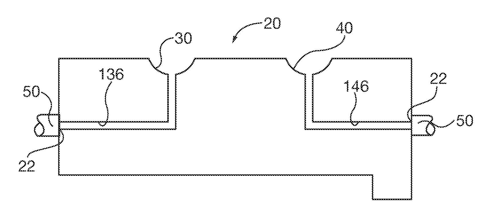
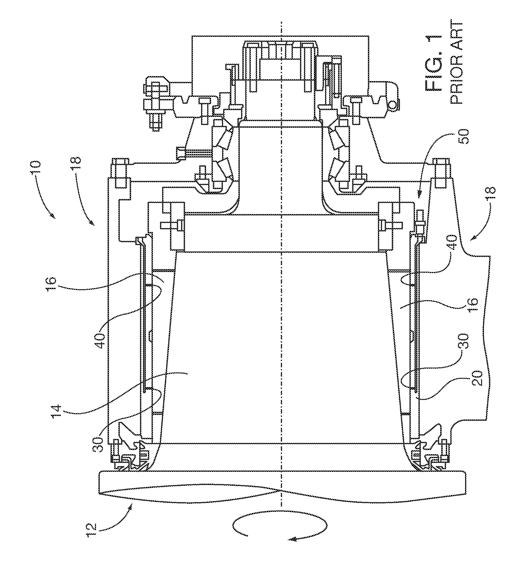
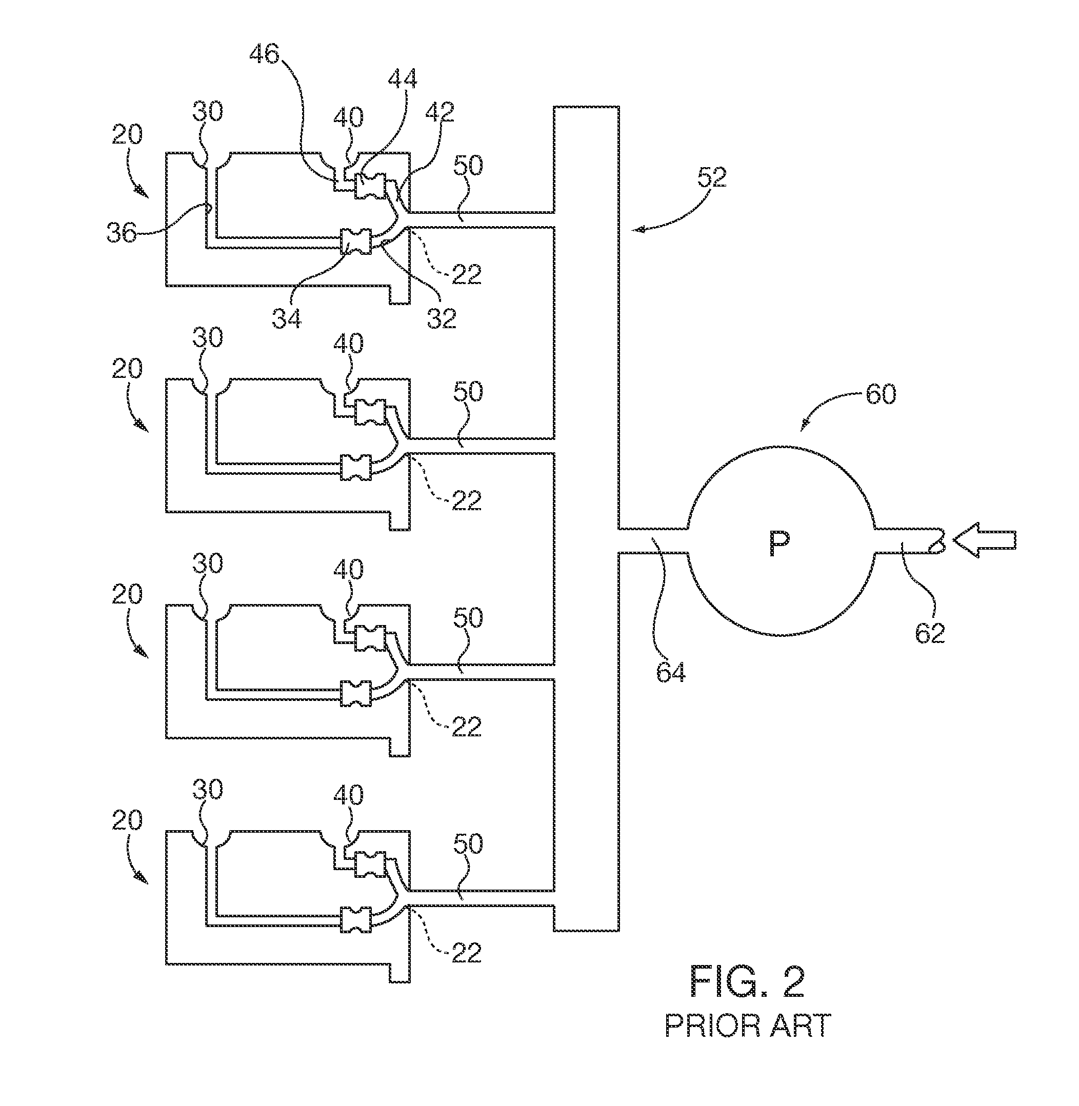
[0023]The general structural and operation of a rolling mill stand, its associated roller support bearings including hydrostatic bearing pads, and pressurized oil supply system commonly shared by multiple bearing pads has been previously described herein with reference to FIGS. 1 and 2, as well as in the previously incorporated by reference U.S. Pat. Nos. 5,000,584 and 6,468,194. FIGS. 3, 4 and 4A show embodiments of hybrid bearing bushings 20 of the present invention. The bearing bushing 20 has a generally annular bushing shell having an inner diameter surface 24 with a known babbit bearing lining material that is capable of forming a self-generating hydrodynamic lubricant film in cooperation...


PUM

PropertyMeasurementUnit
pressureaaaaaaaaaa
inner diameteraaaaaaaaaa
diameteraaaaaaaaaa

Abstract

Rolling mill bearings incorporate bearing bushings with pluralities of hydrostatic pad recesses, that are preferably in conjunction hydrodynamic bearings also formed within the bushing. Each recess has an isolated lubricant passage that is adapted for coupling to a separate isolated source of pressurized lubricant. In some embodiments herein, the isolated pressurized lubricant source is supplied by a dedicated outlet of a pressure pump. In this manner each hydrostatic pad recess has a dedicated pressurized lubricant supply that is not interrupted by loss of lubricant pressure events in other bearing pads or elsewhere within the rolling mill lubrication system.

Description

BACKGROUND[0001]1. Field[0002]Embodiments of the present invention relate to rolling mill stand fluid lubricated bearings supporting roll necks of rotating rollers that are used to roll metals into elongated webs. More particularly, embodiments of the present invention relate to hybrid bearings having hydrostatic fluid bearing pads within hydrodynamic bearing bushings and lubrication systems that provide an isolated source of pressurized lubricant to each respective bearing pad.[0003]2. Description of the Prior Art[0004]FIG. 1 shows a known rolling mill stand bearing assembly 10 that is rotatively supporting a rotating mill roll 12 by a roll neck section 14 and a complimentary rotating bearing sleeve 16. The bearing assembly 10 is supported by a bearing chock 18 that is in turn supported in a mill roll stand (not shown). A bearing bushing 20 is interposed between the roll neck 14 / bearing sleeve 16 and the bearing chock 18 and is fixed in the chock. The bearing bushing 20 provides a ...

Claims


Application Information

Patent Timeline
Patent Type & Authority Applications(United States)
IPC IPC(8): B21B27/08F16C32/06
CPCF16C32/0685F16C17/02F16C2322/12B21B31/074F16C33/107F16C32/0659F16C32/0666
Inventor WILLIAMS, MORTIMERWOJTKOWSKI, JR., THOMAS C.MASE, ROBERTOSGOOD, PETER N.
Owner PRIMETALS TECH USA
Why Eureka
Try Eureka