Signal and power transmission system

a power transmission system and signal technology, applied in the direction of transmission, power distribution line transmission, drill/well adaptable systems, etc., can solve the problems of transformers becoming excessively large, increasing the size of the drive circuit and the number of components of the drive circuit, etc., to increase the size of the drive circuit and the number of components.

Inactive Publication Date: 2013-04-04
DENSO CORP
View PDF12 Cites 26 Cited by
  • Summary
  • Abstract
  • Description
  • Claims
  • Application Information

AI Technical Summary

Benefits of technology

[0006]However, when the known drive circuit is used as a drive circuit for each switching element of a three-phase inverter, the transformer needs be provided for at least each leg of the power converter. That is, an increase in the number of elements to be driven by the drive circuit may increase the size of the drive circuit and the number of components of the drive circuit.
[0012]With the exemplary aspect of the present disclosure, the target signal is encoded into the pulse code signal. Thus, it is possible to easily transmit the target signal via the primary coil and the secondary coil to a given destination. Because the input voltage signal is based on the pulse code signal, the output voltage signal is a pulsed voltage signal. Thus, it is possible to easily detect the target signal based on the variation in the pulsed output voltage signal, thus easily decoding the pulsed output voltage signal into the target signal using the variation in the pulsed output voltage signal. In addition, the output voltage signal is rectified by the rectifier, so that a rectified current is generated. Thus, it is possible to use the rectified current as a DC power source in the destination.

Problems solved by technology

That is, an increase in the number of elements to be driven by the drive circuit may increase the size of the drive circuit and the number of components of the drive circuit.
Thus, if another power source is required for other uses other than driving the switching element in the known drive circuit, it may be difficult to use the pair of first and second capacitors, resulting in the need to provide another power source.
An increase in on duration or off duration to be instructed for the switching element in the known drive circuit may cause interlinkage flux to the primary coil or the secondary coil of the transformer to become excessively large, resulting in the need of upsizing of the transformer.

Method used


Image

  • Signal and power transmission system
  • Signal and power transmission system
  • Signal and power transmission system

Examples


first embodiment

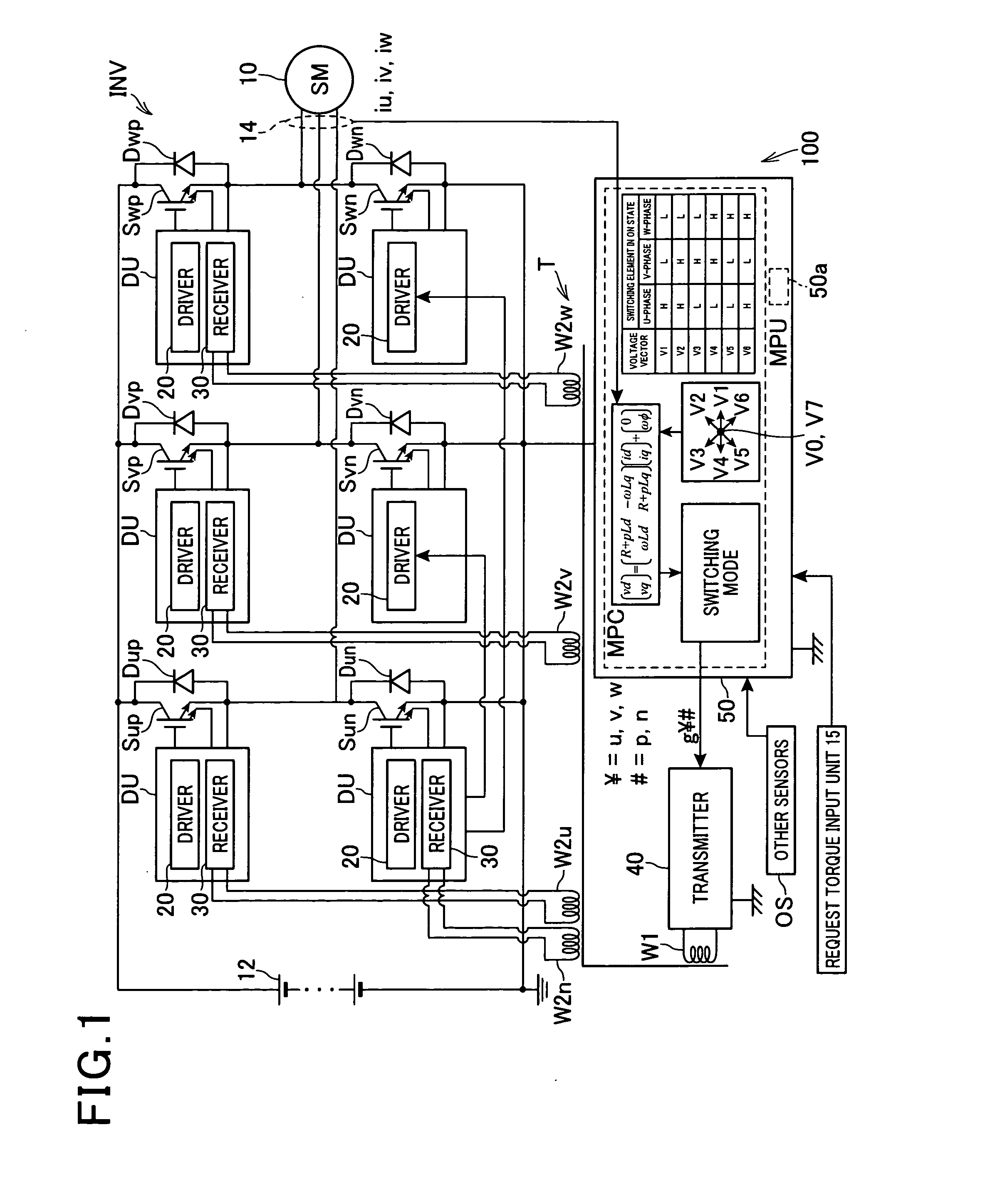
[0042]Referring to FIG. 1, there is illustrated a three-phase motor-generator as an example of rotating machines, referred to simply as a “motor-generator”10, installed in, for example, a motor vehicle as a main engine according to the first embodiment. As the motor-generator 10, a motor having a salient-pole structure is used. For example, as the motor-generator 10, a three-phase SM (Synchronous Motor) is used.

[0043]In FIG. 1, there is also illustrated a control system 100. The control system 100 is equipped with an inverter INV serving as a circuit for applying a variable output voltage to the motor-generator 10, a high-voltage battery 12 as an example of DC power sources, drive units DU, a transmitter 40, a transformer T, and a microprocessor unit (MPU) 50.

[0044]To the motor-generator 10, the high-voltage battery 12 is electrically connected via the inverter INV. The high-voltage battery is for example a secondary battery with the terminal voltage, which is, for example, equal to...

second embodiment

[0151]A signal and power transmission system according to the second embodiment of the present disclosure will be described with reference to FIG. 9.

[0152]The structure and / or functions of the signal and power transmission system according to the second embodiment are mainly identical to those of the signal and power transmission system according to the first embodiment except for the following points. So, the different points will be mainly described hereinafter.

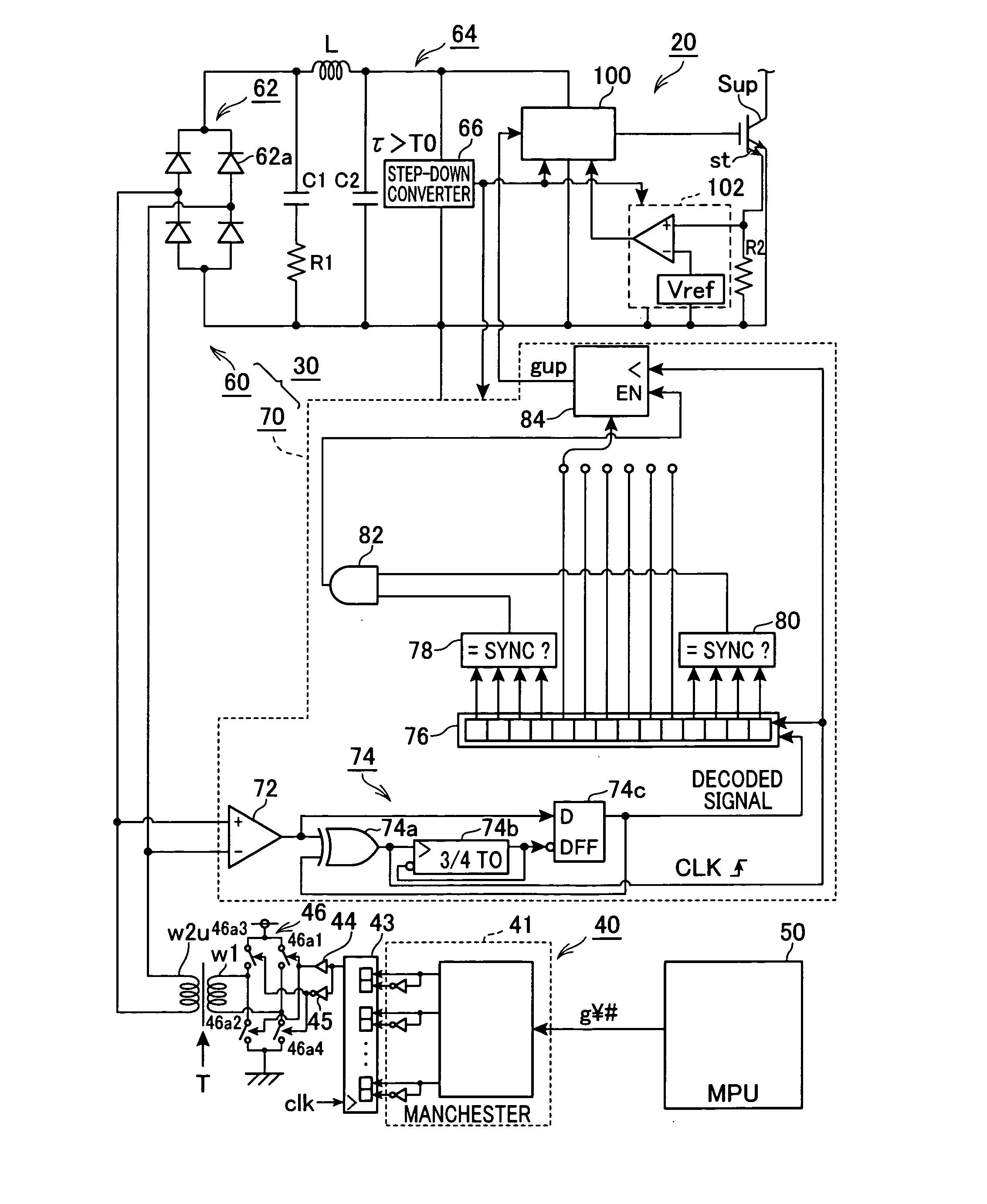
[0153]The signal and power transmission system according to this embodiment is configured to disable updating of drive signals g¥# if a decoded signal stored in the shift register 76 includes a pair of bits representing that the corresponding pair of high-side and low-side drive signals g¥p and g¥n of one same leg are ON commands. If such a state is continued for given cycles of transmission of drive signals g¥#, the signal and power transmission system according to this embodiment is configured to forcibly turn off all the...

third embodiment

[0161]A signal and power transmission system according to the third embodiment of the present disclosure will be described with reference to FIGS. 10 and 11.

[0162]The structure and / or functions of the signal and power transmission system according to the third embodiment are mainly identical to those of the signal and power transmission system according to the first embodiment except for the following points. So, the different points will be mainly described hereinafter.

[0163]FIG. 10 schematically illustrates a parallel-series hybrid vehicle in which a first motor-generator 10a and a second motor-generator 10b are installed. Each of the first and second motor-generators 10a and 10b has the same structure as the motor-generator 10. In FIG. 10, there is also illustrated a control system 100A. The control system 100A is equipped with a pair of inverters INVa and INVb, and a converter CNV. The motor-generators 10a and 10b are connected to the converter via the respective inverters INVa ...


PUM


Abstract

In a signal and power transmission system, a primary coil and a secondary coil magnetically coupled to the primary coil and connected to an electrical path are provided. An encoder encodes a target signal to be transmitted to produce a pulse code signal, and a voltage applying unit applies a voltage signal based on the pulse code signal to the primary coil as an input voltage signal. A decoder decodes an output voltage signal induced in the secondary coil using a variation in the output voltage signal into a decoded signal corresponding to the target signal. The output voltage signal is induced in the secondary coil based on the input voltage signal. A rectifier rectifies a current flowing through the electrical path connected to the secondary coil according to the output voltage signal induced in the secondary coil, thus outputting a rectified current as power.

Description

CROSS REFERENCE TO RELATED APPLICATIONS[0001]This application is based on and claims the benefit of priority from Japanese Patent Applications 2011-208540 and 2012-120878 filed on Sep. 26, 2011 and May 28, 2012, respectively, the disclosure of each of which is incorporated in its entirety herein by reference.TECHNICAL FIELD[0002]The present disclosure relates to signal and power transmission systems for transmitting signals and power to a destination.BACKGROUND[0003]Japanese Patent Publication No. 3417127 discloses a drive circuit for a power converter. In the known drive circuit, a first frequency signal and a second frequency signal are outputted while they are switched at every preset period. The first and second frequency signals are alternately applied to the primary coil of a transformer, so that different voltages based on the first and second frequency signals are alternately induced across the secondary coil of the transformer with the secondary coil and the primary coil be...

Claims


Application Information

Patent Timeline
Patent Type & Authority Applications(United States)
IPC IPC(8): H02J4/00
CPCH02J4/00H04B2203/5475H04B3/548
Inventor YAMAGUCHI, NOBUHISA
Owner DENSO CORP
Why Eureka
Try Eureka