Nuclear magnetic resonance imaging apparatus and nuclear magnetic resonance imaging method

Inactive Publication Date: 2013-04-04
CANON KK
View PDF1 Cites 36 Cited by
  • Summary
  • Abstract
  • Description
  • Claims
  • Application Information

AI Technical Summary

Benefits of technology

[0009]The present invention is directed to a nuclear magnetic resonance imaging apparatus and a nuclear magnetic resonance imaging method that avoid a region with zero sensitivity of an optical m

Problems solved by technology

However, conditions has not been clarified required for avoiding a region with zero sensitivity of the optical magnetometer, and for imaging by strong magnet

Method used


Image

  • Nuclear magnetic resonance imaging apparatus and nuclear magnetic resonance imaging method
  • Nuclear magnetic resonance imaging apparatus and nuclear magnetic resonance imaging method
  • Nuclear magnetic resonance imaging apparatus and nuclear magnetic resonance imaging method

Examples


example 1

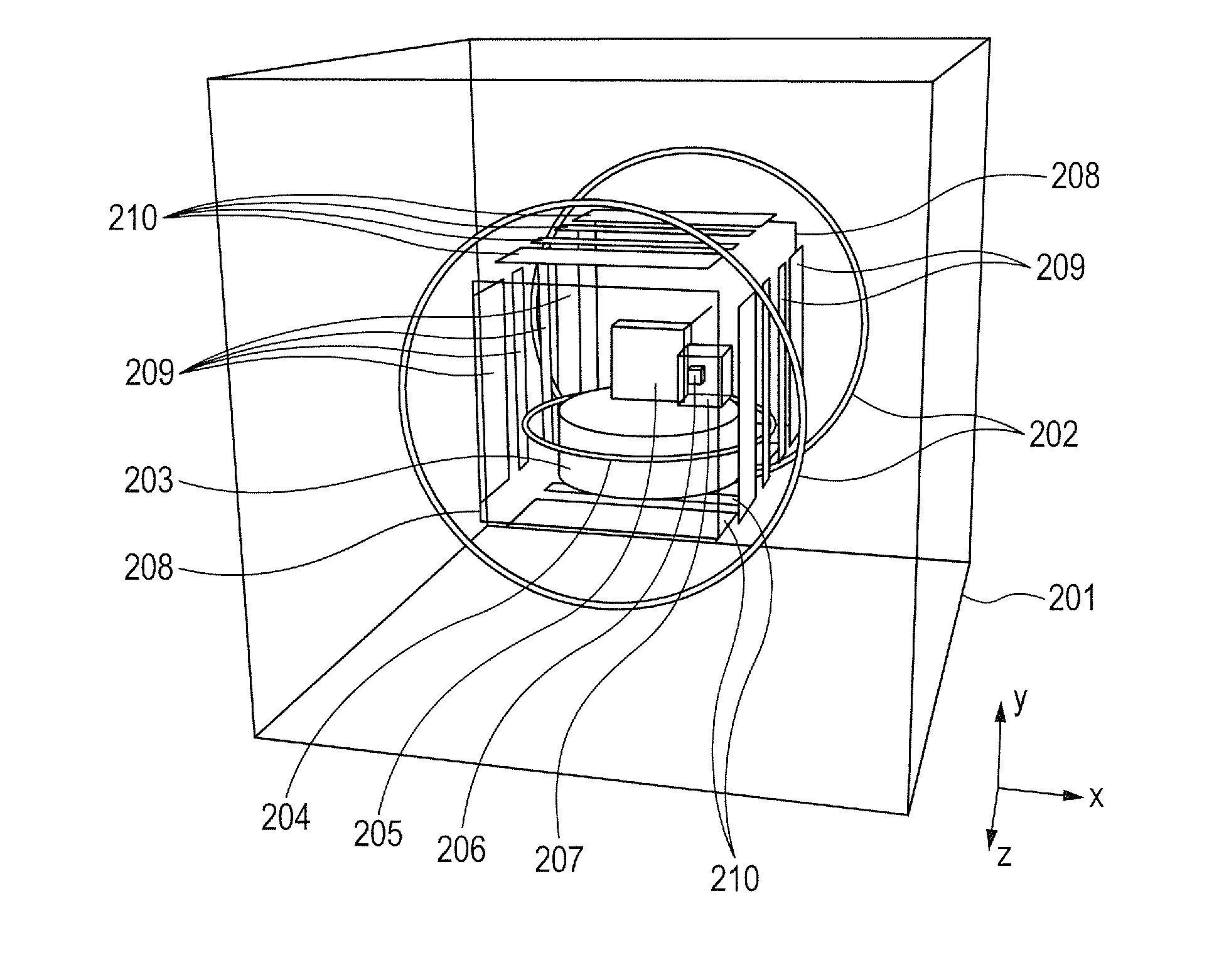
[0046]As Example 1, an exemplary configuration of a nuclear magnetic resonance imaging apparatus to which the present invention is applied will be described with reference to FIG. 4. As illustrated in FIG. 4, the nuclear magnetic resonance imaging apparatus in this Example is surrounded by three pairs of coils 201 directed in three axis directions to cancel earth's magnetic field. Further, the nuclear magnetic resonance imaging apparatus includes a pair of Helmholtz coils 202 for applying a magnetostatic field to a sample. The pair of coils 202 apply a magnetostatic field B0 having intensity of, for example, about 50 μT to 200 μT. A polarization coil 203 generates a magnetic field in a direction perpendicular to the magnetostatic field B0 to cause spin polarization of the sample. The polarization coil 203 applies a magnetic field of, for example, 40 mT to 100 mT. An RF coil 204 applies a 180° pulse or a 90° pulse to the sample to control a direction of the spin of the sample. The en...

example 2

[0067]As Example 2, an exemplary configuration with a shape of a region to be imaged different from that in Example 1 will be described with reference to FIG. 8A and FIG. 8B showing a side view thereof.

[0068]In Example 1, for a region to be imaged, a sectional shape of a region in the z direction is a thin plate-like shape, and a sectional shape in an in-plane direction perpendicular to the z direction is a square shape with a size larger than a thickness of the thin plate on a side.

[0069]On the other hand, in this Example, for a region to be imaged, a sectional shape in the in-plane direction perpendicular to the z direction is a thin plate-like shape, and a sectional shape of a region in the z direction is a square shape with a size larger than a thickness of the thin plate on a side. Specifically, as shown in FIG. 8A, the region is a thin plate-like region in the y direction.

[0070]Also in this case, there is the same restriction as described in the embodiment. Specifically, when ...

example 3

[0072]In Example 3, an exemplary possible arrangement of sensors when it is found that a sample in a space to be imaged does not completely fill the space to be imaged and there is a region only with air in an image will be described with reference to FIG. 9A and FIG. 9B showing a side view thereof.

[0073]For example, when the region to be imaged includes an elliptic cylindrical sample region in the region to be imaged, specifically, when a space to be imaged 205 includes an elliptic cylindrical sample, the sensors are arranged as in FIG. 9A. Specifically, the sensor module 207 is arranged along a side surface of the elliptic cylinder, and thus if the cell enter the space to be imaged, the cell does not become an obstacle in practice. As shown in FIG. 9A, the cell 206 is arranged so as not to intersect the sample within a plane (x-y plane in FIG. 9B) perpendicular to the magnetostatic field, thereby allowing configuration of an image. The alkali metal cell 206 is arranged so that coo...


PUM


Abstract

The present invention has an object to provide a nuclear magnetic resonance imaging apparatus or the like that avoids a region with zero sensitivity of an optical magnetometer and allows imaging by strong magnetic resonance when a common magnetic field is used as a bias field of an optical magnetometer and as a magnetostatic field to be applied to a sample. When a direction of a magnetostatic field application unit applying a magnetostatic field to a sample is a z direction, alkali metal cell of a scalar magnetometer is arranged so as not to overlap a region to be imaged in a z direction, and so as not to intersect the region to be imaged in an in-plane direction perpendicular to the z direction.

Description

BACKGROUND OF THE INVENTION[0001]1. Field of the Invention[0002]The present invention relates to a nuclear magnetic resonance imaging apparatus and a nuclear magnetic resonance imaging method.[0003]2. Description of the Related Art[0004]An optical magnetometer with high sensitivity, using electron spin of an alkali metal gas, has been proposed. When the optical magnetometer is used to measure magnetic resonance (perform magnetic imaging), a relationship between a bias field for operating the magnetometer and a magnetostatic field to be applied to a sample is restricted in some extent. This is because a Larmor frequency ω0 of alkali metal or proton is ω0=γA|B| in proportion to magnitude |B| of a magnetic field. A constant of proportion γA is referred to as a gyromagnetic ratio. A gyromagnetic ratio of nuclear spin of proton is smaller than a gyromagnetic ratio of electron spin of alkali metal, for example, a gyromagnetic ratio of proton is about 1 / 167 of a gyromagnetic ratio of potas...

Claims


Application Information

Patent Timeline
IPC IPC(8): G01R33/48
CPCG01R33/482G01R33/26
Inventor MIZUTANI, NATSUHIKOKOBAYASHI, TETSUOISHIKAWA, KIYOSHI
Owner CANON KK
Why Eureka
Try Eureka