
Method for identifying stimulation target

a stimulation target and target technology, applied in the field of stimulation target identification, can solve the problems of “on-off” alternating reaction, affecting the normal life of patients, and affecting the quality of life, and achieve the effect of quick and efficient identification

Active Publication Date: 2013-04-04
NAT CHIAO TUNG UNIV
View PDF9 Cites 14 Cited by
  • Summary
  • Abstract
  • Description
  • Claims
  • Application Information

AI Technical Summary

Benefits of technology

The present invention provides a method for accurately identifying the boundary of a stimulation target and the precise positions of implanted probes, which increases accuracy during surgeries. This is achieved by using a combination of computed tomography and magnetic resonance imaging to guide the implantation of composite probes and measure electrical potentials to delineate tissue structures surrounding the probes. This method allows for faster and more efficient identification of the precise locations of the probes, resulting in improved efficacy of the procedures.

Problems solved by technology

Side effects often appear after patients have taken medicines, and one of the most common side effects is dyskinesia, which not only hinders a normal life, and may also induce a variety of symptoms of Parkinson's disease.
In addition to drug-induced side effects, after the drug has been taken for a long period of time, it may often lose efficacy and often induce an “on-off” alternating reaction.
When the drug induces the “on” reaction, the patient's symptom is under control, but when the “off” reaction is induced, the patient's symptoms will not be able to be controlled, and thus the ability to lead a normal life is affected.
However, the microelectrode recording technique can be used only to determine whether the depth of implanted probe has reached the stimulation target, but cannot be used to determine the exact location of the probe within the stimulation target.
Therefore, it is possible that the permanent wire is placed at the non-optimal position within the stimulation target rather than being properly implanted at the “optimal location” within the stimulation target.
If the placement position is not ideal for the permanent wire, the part of the target within the brain that is stimulated upon electrical conduction will be limited, and thus cannot achieve the desired effect of the surgery.
However, this prior-art technique still cannot determine if the implant position of the probe is accurate or not, so several trajectories for implanting the probe may still be required to locate the best implant position, so a fast and accurate implantation of the probe into the desired location of the stimulation target is not possible, which increases the burden on the patient and surgical risks of failure.
If one wishes to delineate the tissue structures surrounding of the probe in a DBS surgery so as to know the precise location of the probe implanted in the target, the electrical impedance tomography technique is not directly applicable.

Method used


Image

  • Method for identifying stimulation target
  • Method for identifying stimulation target
  • Method for identifying stimulation target

Examples


Embodiment Construction

[0019]The present invention is described by the following specific embodiments. Those with ordinary skills in the arts can readily understand the other advantages and functions of the present invention after reading the disclosure of this specification. The present invention can also be implemented with different embodiments. Various details described in this specification can be modified based on different viewpoints and applications without departing from the scope of the present invention.

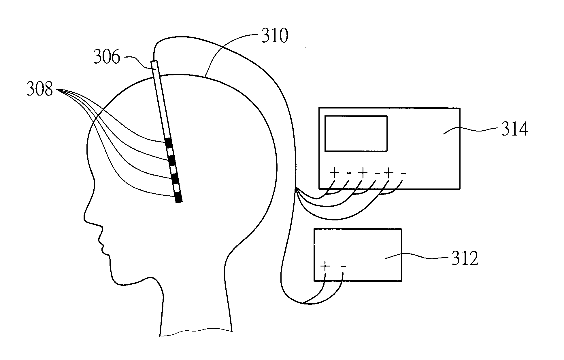
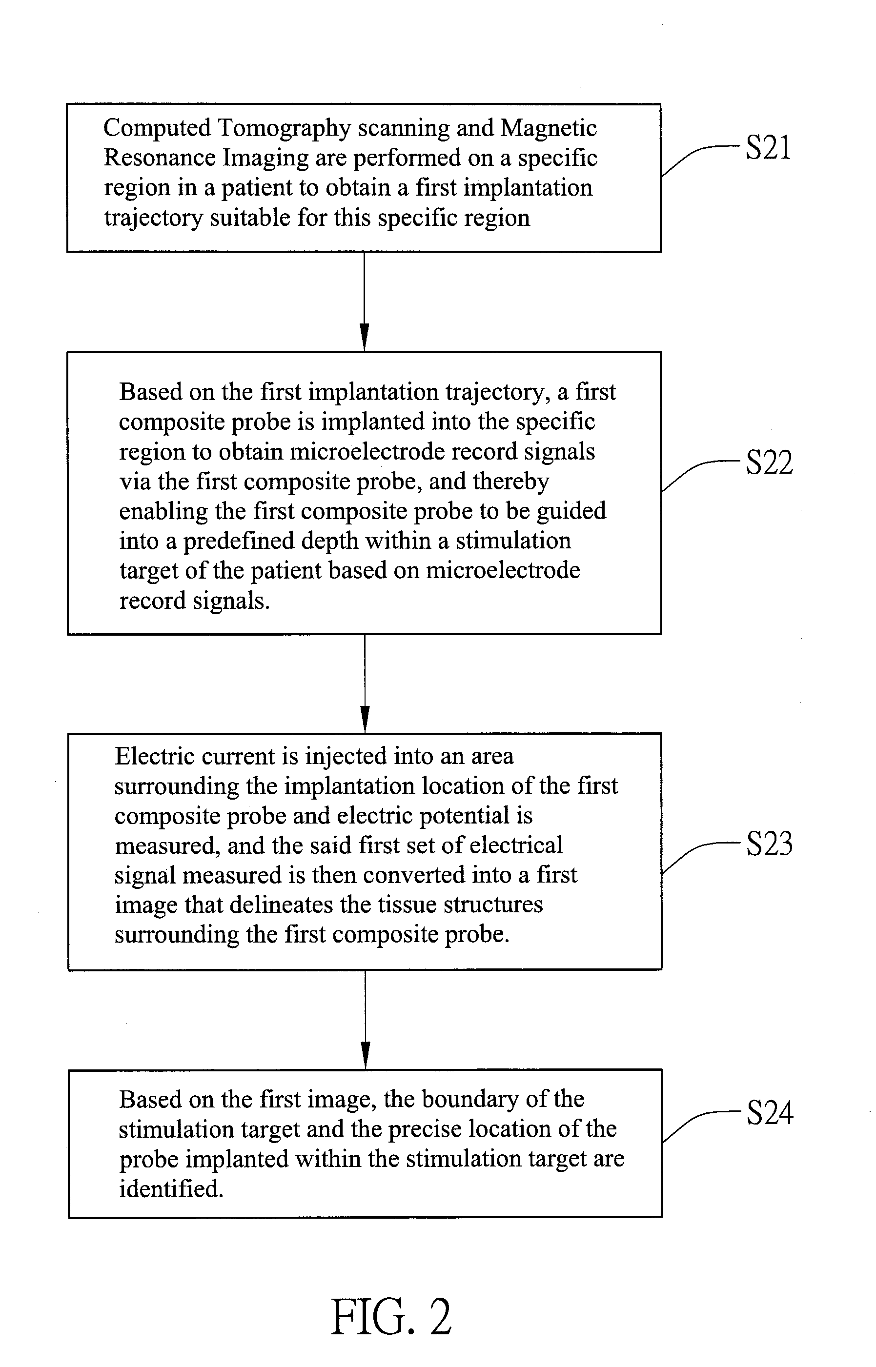
[0020]The steps of method for identifying the stimulation target applicable to deep brain stimulation (DBS) according to an embodiment of the present invention are shown in FIG. 2.

[0021]As shown, in step S21, Computed Tomography (CT) scanning and Magnetic Resonance Imaging (MRI) are performed on a specific region in the patient to obtain a first implantation trajectory suitable for this specific region, then step S22 is performed.

[0022]In an embodiment of the present invention, step S21 can be i...


PUM


Abstract

A method for identifying a stimulation target is provided, which uses microelectrode recording and electrical impedance tomography techniques together in a composite probe. The composite probe includes at least a microelectrode recording sensor and a plurality of microelectrodes, so that after the composite probe is guided and implanted to a depth suitable for the stimulation target based on microelectrode recording signals, tissue structures surrounding the composite probe are delineated by using the plurality of microelectrodes, and the boundary of the stimulation target and the precise location of the composite probe within the stimulation target are determined. Accordingly, the present invention provides a quick and accurate direction for surgeons, eliminating the problem of not knowing the exact location of the implanted probe within the stimulation target as in the case during deep brain stimulation surgeries.

Description

FIELD OF THE INVENTION[0001]The present invention relates to a method for identifying stimulation targets, and more particularly, to a method for identifying stimulation targets applicable to deep brain stimulation (DBS).BACKGROUND OF THE INVENTION[0002]Side effects often appear after patients have taken medicines, and one of the most common side effects is dyskinesia, which not only hinders a normal life, and may also induce a variety of symptoms of Parkinson's disease.[0003]In addition to drug-induced side effects, after the drug has been taken for a long period of time, it may often lose efficacy and often induce an “on-off” alternating reaction. When the drug induces the “on” reaction, the patient's symptom is under control, but when the “off” reaction is induced, the patient's symptoms will not be able to be controlled, and thus the ability to lead a normal life is affected.[0004]Therefore, when the patient cannot carry out normal activities or quality of life is affected due t...

Claims


Application Information

Patent Timeline
Patent Type & Authority Applications(United States)
IPC IPC(8): A61B6/03A61B5/055A61N1/05A61B5/053
CPCA61B6/12A61B6/032A61B5/0538A61B5/0536
Inventor CHOI, CHARLES TAK MINGSUN, SHU-HAILEE, YI-HSUAN
Owner NAT CHIAO TUNG UNIV
Learn More