Ultrasound transducer, ultrasound probe, and ultrasound diagnostic apparatus

Inactive Publication Date: 2013-04-04
KONICA MINOLTA MEDICAL & GRAPHICS INC
View PDF2 Cites 12 Cited by
  • Summary
  • Abstract
  • Description
  • Claims
  • Application Information

AI Technical Summary

Benefits of technology

The present invention provides an ultrasound transducer that can output a higher resonance component or a higher voltage at the time of transmission compared to the primary resonance component. This is achieved by intercalating layers of piezoelectric materials with electrodes between them and on both end surfaces. A de-matching layer is provided on the opposite surface of the transmission to reflect vibrations and increase the output sound pressure. The piezoelectric materials have a remanent polarization in a thickness direction, and a basic relationship is established between the direction of the electrical displacement and the remanent polarization. The piezoelectric layers are periodically arranged to have the same relationship with the basic relationship. The ultrasound transducer can be used in an ultrasound probe and can provide higher output sound pressure and improved ultrasound imaging.

Problems solved by technology

Moreover, the thinner piezoelectric material makes a manufacturing process difficult such as thickness control, or handling.
However, sensitivity of higher resonance component is weaker compared with a primary resonance component and is easy to decrease by dumping of a piezoelectric material or circumference material, whereby mere is problem that it is hardly to obtain the signal with a high S / N ratio.
As mentioned above, the problems of the conventional technology are that an apparent electromechanical coupling coefficient decreases to 1 / n when detects n-th resonance component, and that an electrical impedance is unambiguously decided by the dimension of a piezoelectric material.

Method used


Image

  • Ultrasound transducer, ultrasound probe, and ultrasound diagnostic apparatus
  • Ultrasound transducer, ultrasound probe, and ultrasound diagnostic apparatus
  • Ultrasound transducer, ultrasound probe, and ultrasound diagnostic apparatus

Examples


example 1

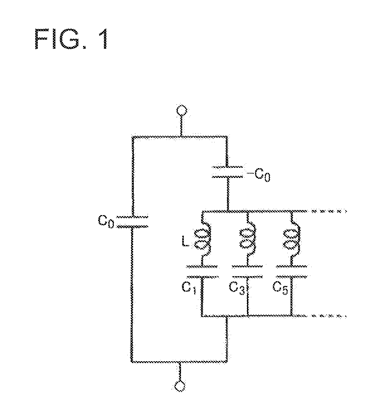
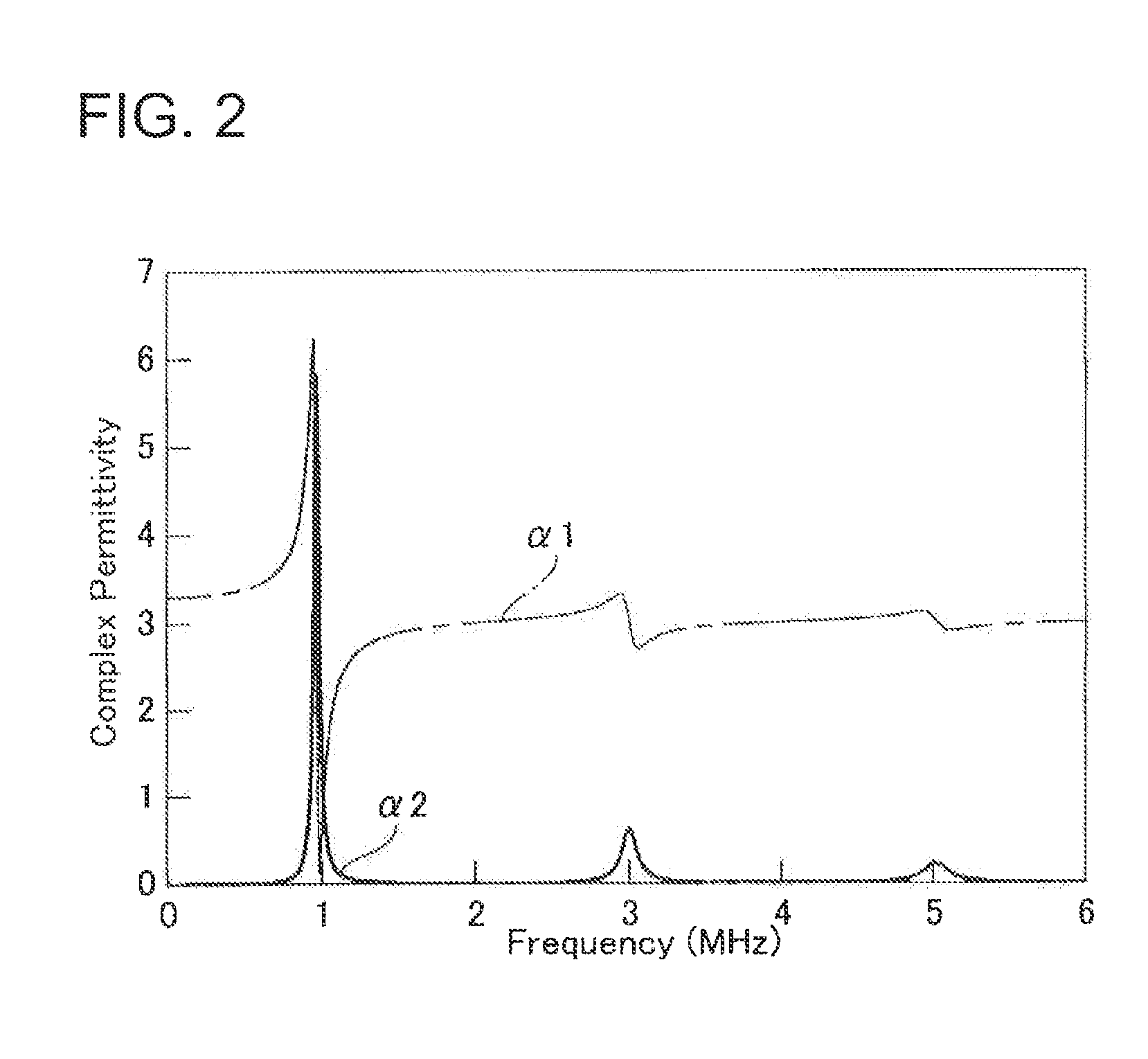
[0103]Examples according to an above-mentioned view will be detailed below. At first, detection of 3λ / 4 resonance component by 2-layer piezoelectric transducer shown in FIG. 10 will be described as the 1st example. A 2-layer piezoelectric transducer has the simplest structure in a laminated piezoelectric material. In this case, the order of the resonance component is not in agreement with the lamination number used for a transmission-and-rejection. However, the efficiency of a transmission-and-reception can be raised by applying the present invention as follows.

[0104]The strains S1 and S2 of the piezoelectric materials 1 and 2 of FIG. 10 each is:

S1=Δh1 / h1=ξ0 sin(nπ / 2−h1 / h) / h1  (24)

S2=Δh2 / h2=ξ0 { sin(nπ / 2)−sin(nω / 2−h1 / h)} / h2  (25).

[0105]Herein, h represents a height of a laminated piezoelectric material, h1 and h2 each represents a height of each piezoelectric material, and h1=h2=h / 2.

[0106]The response to 3λ / 4 resonance component is given by n=3. In that case, strain S13ω and S22ω ea...

example 2

[0115]Subsequently, detection of the 3rd resonance component by a 3-layer piezoelectric transducer will be described. Schematic structural drawing is shown in FIG. 14. This transducer is a λ / 4 transducer which fixes the one end of a laminated piezoelectric material to a de-matching layer, and another end is a free end.

[0116]Design process based on the present invention will be described first. Similar to above description, the coordinate of the height (thickness) direction of an element is set to z based on the boundary of a de-matching layer and a piezoelectric material 1 as the origin. Next, strain S occurred on each piezoelectric material will be considered. The piezoelectric material 1, the piezoelectric material 2, and the piezoelectric material 3 are laminated in this order from the base side. Coordinate z is set as Z=0 at the boundary of the base and the piezoelectric material 1, to z1 at the boundary of the piezoelectric material 1 and the piezoelectric material 2, to z2 at ...

example 3

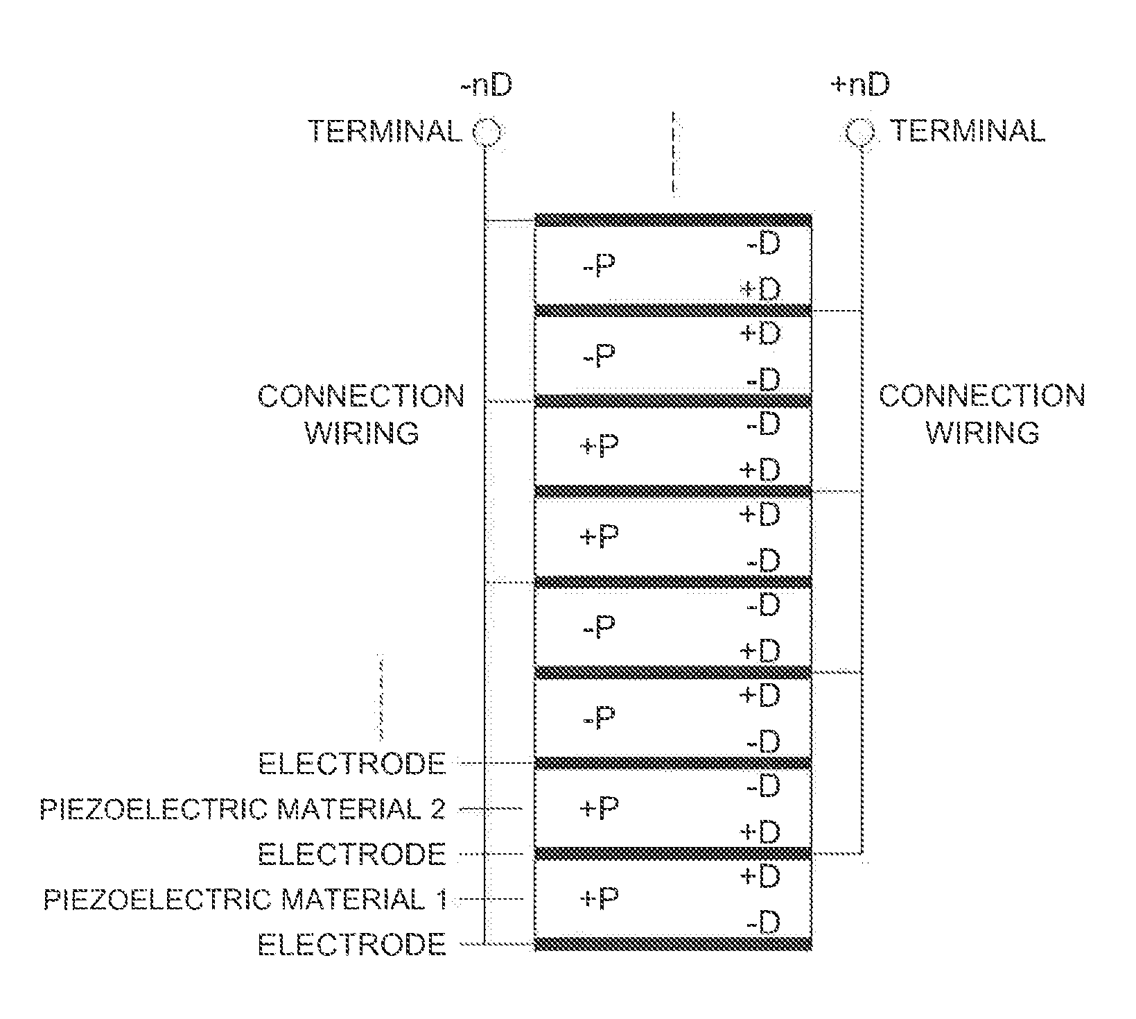
[0132]The 3rd example is related to a transmission and reception of the 3rd resonance component by the transducer laminated with 6 layers of piezoelectric materials having the same thickness. This example corresponds to the case in which each piezoelectric material of 3-layer piezoelectric transducer shown in the 2nd example is further divided into two piezoelectric materials. In the case of parallel connection, since electrical impedance not only becomes half further, but an electrode at upper end surface and an electrode at lower end surface are connected, whereby the whole laminated piezoelectric material can be shielded electrically.

[0133]FIG. 19 is sectional drawing in which showing the structure of the 6-layer piezoelectric transducer, and schematically showing a displacement and a strain at the time of the transmission-and-reception of the 3rd resonance component. FIG. 19a shows a lamination status. FIG. 19b shows a displacement of each layer at a certain moment and FIG. 19c ...


PUM


Abstract

Object is that an output sound pressure at transmission or an output voltage at reception of a predetermined higher resonance component becomes higher than those of the primary resonance component. The piezoelectric material layer 24 has an electrode on the surface of the piezoelectric material of between the layer and both ends, and outputs and inputs an electrical signal with this electrode. The piezoelectric material 24 has a remanent polarization in a thickness direction, the relationship of the (4P+1)th layer piezoelectric material from fixed end side is used as the basic relationship, piezoelectric materials are periodically arranged so that piezoelectric materials of (4p+2)th and (4p+3)th layer each has an opposite relationship, and (4p+4)th layer has the same relationship as the basic relationship. On the fixed-end side of the piezoelectric material layer 24, provided is the de-matching layer 23 with larger acoustic impedance than the piezoelectric material layer 24 for reflecting vibration propagated from the piezoelectric material layer 24 to the fixed-end side.

Description

[0001]This application is based on Japanese Patent Application No. 2011-216053 filed on Sep. 30, 2011 in Japan Patent Office, the entire content of which is hereby incorporated by reference.FIELD OF THE INVENTION[0002]The present invention relates to an ultrasound transducer, an ultrasound probe, and ultrasound diagnostic imaging apparatus.TECHNICAL BACKGROUND[0003]Generally a piezoelectric material is used for an ultrasound transducer (ultrasonic transducer), since the piezoelectric material has a function to transform kinetic energy into electric energy or vice versa, what is called as a binding action between electrical system and mechanical system. Used piezoelectric material has the shape of a sheet, tabular or cylindrical having a pair of electrode in which one electrode is feed to a back layer, and another electrode contacts to medium through an acoustic lens or a matching layer.[0004]Most of piezoelectric ultrasound transducers emit a sound wave to a medium by d33 mode or e3...

Claims


Application Information

Patent Timeline
IPC IPC(8): A61B8/13H01L41/09H01L41/04
CPCA61B8/4483H01L41/083H01L41/257H01L41/187H01L41/193H01L41/183B06B1/0611H10N30/50H10N30/045H10N30/852H10N30/853H10N30/857
Inventor NISHIKUBO, YUICHI
Owner KONICA MINOLTA MEDICAL & GRAPHICS INC
Why Eureka
Try Eureka