
Methods for in-situ chamber clean utilized in an etching processing chamber

a plasma processing chamber and in-situ cleaning technology, which is applied in the direction of cleaning using liquids, coatings, chemistry apparatus and processes, etc., can solve the problems of affecting the overall substrate etching performance, affecting the ability to maintain process control, and becoming a source of unwanted particles that may contaminate the substra

Active Publication Date: 2013-04-11
APPLIED MATERIALS INC
View PDF7 Cites 29 Cited by
  • Summary
  • Abstract
  • Description
  • Claims
  • Application Information

AI Technical Summary

Benefits of technology

The patent text describes methods for cleaning a plasma processing chamber used for gate structure fabrication in semiconductor devices. Specifically, the methods involve supplying different cleaning gases into the chamber in the absence of a substrate. The first cleaning gas includes a mixture of a boron containing gas and a fluorine containing gas, the second cleaning gas includes a mixture of a halogen containing gas and the third cleaning gas includes a mixture of oxygen containing gas and a fluorine gas. The methods can effectively clean the chamber and improve the efficiency of the fabrication process.

Problems solved by technology

The metal containing etch by-products may also attack the surfaces of the chamber components, which in turn detrimentally affects the ability to maintain process control during circuit fabrication.
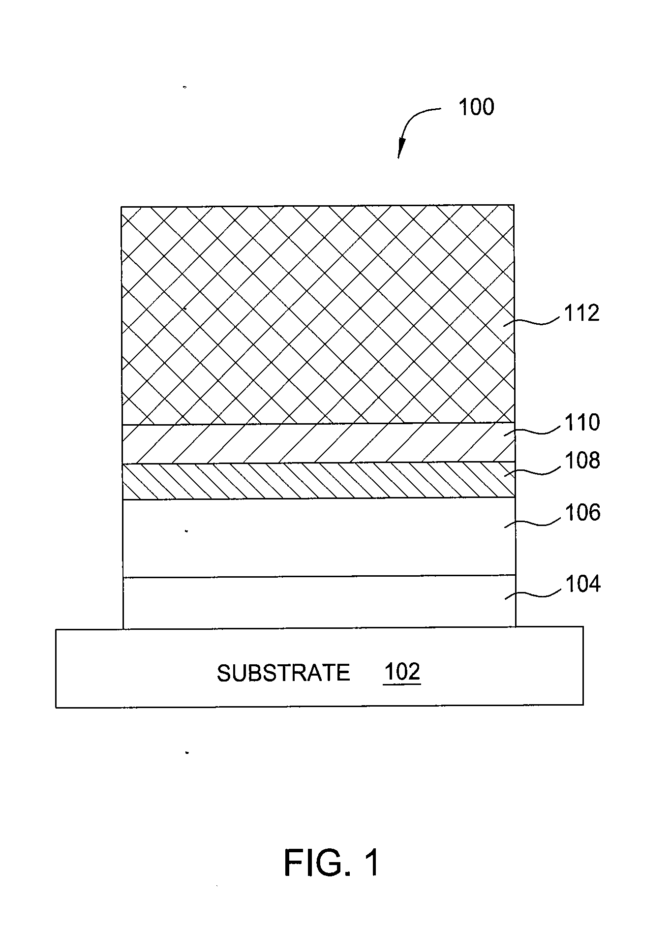
Furthermore, metal containing etching by-products accumulating on components and surfaces of the processing chamber may impact recombination and surface reactions on the chamber walls, thereby affecting the overall substrate etching performance as well as becoming a source of unwanted particles that may contaminate the substrate 102.
When the deposited metal containing etch by-products reach a certain thickness, the by-products may peel off from the inner wall of the plasma chamber and contaminate the substrate 102 by falling onto the substrate, causing irreparable defects to the device structure formed on the substrate.

Method used


Image

  • Methods for in-situ chamber clean utilized in an etching processing chamber
  • Methods for in-situ chamber clean utilized in an etching processing chamber
  • Methods for in-situ chamber clean utilized in an etching processing chamber

Examples


Embodiment Construction

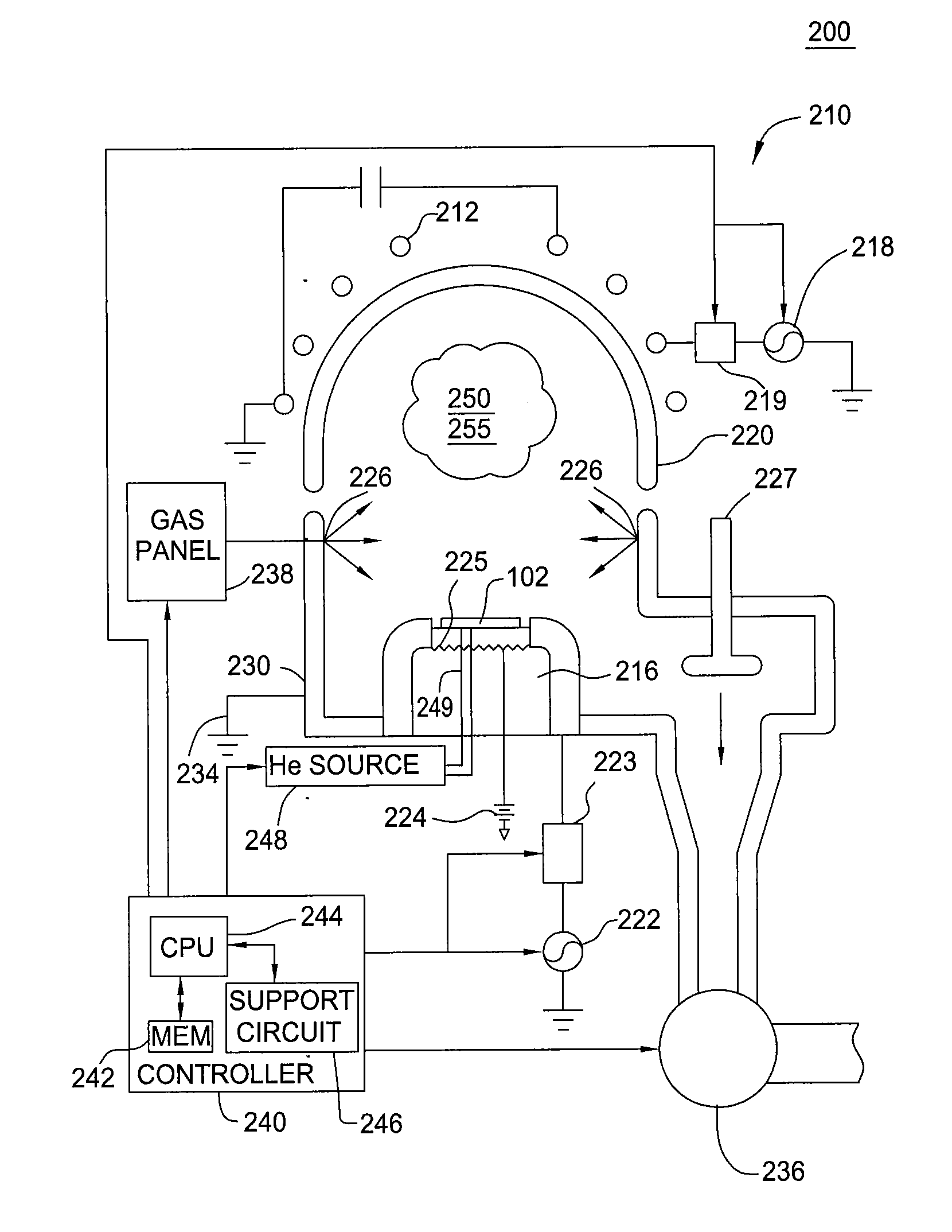
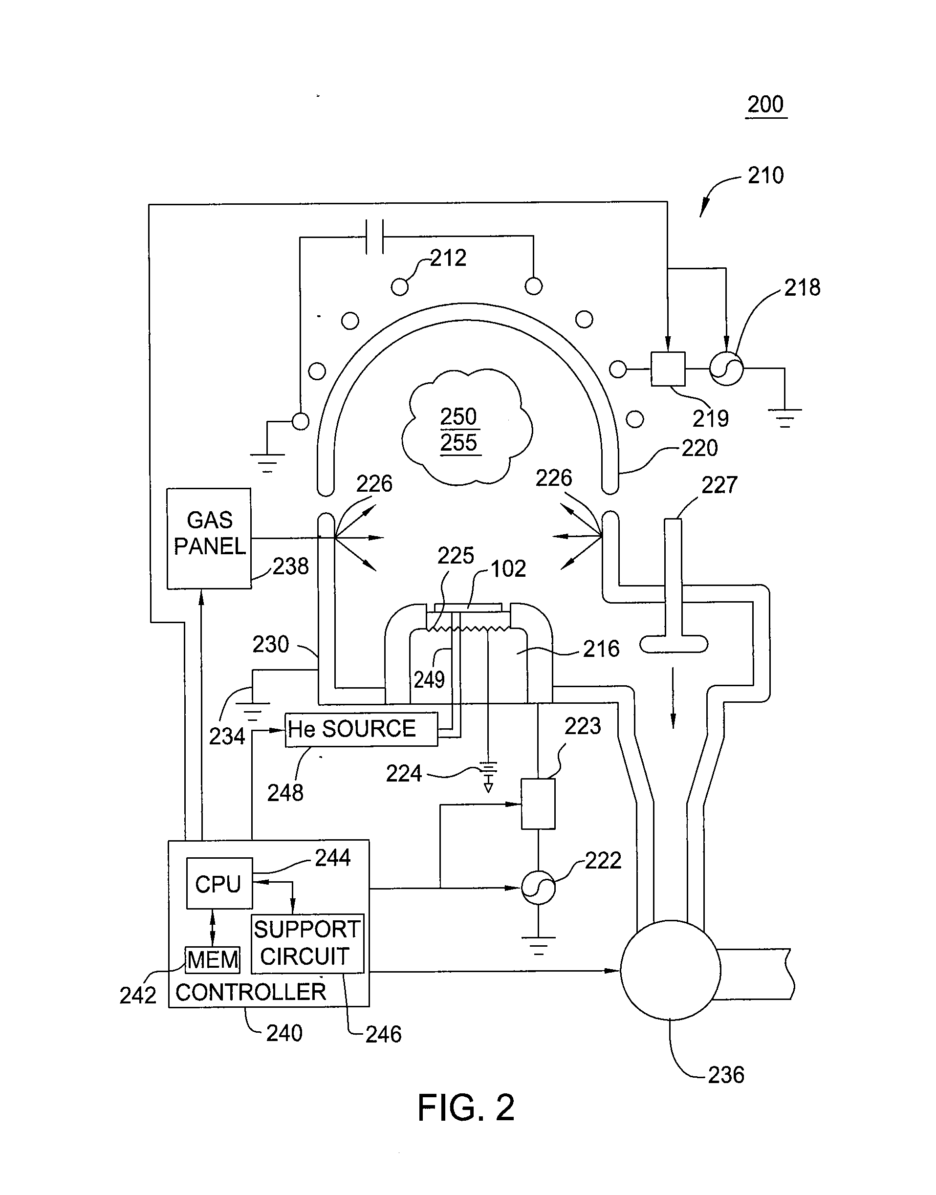
[0016]Embodiments of the present invention provide methods and apparatus for an in-situ chamber clean process utilized to clean a plasma processing chamber. The in-situ cleaning process is beneficial after etching. The in-situ cleaning process efficiently remove etch by-products from the plasma processing chamber without damaging chamber components. In one embodiment, the in-situ cleaning process may be performed in any suitable plasma processing chamber. In an exemplary embodiment, the in-situ cleaning process may be performed in a plasma etch chamber, for example, a Decoupled Plasma Source (DPS), DPS-II, or DPS Plus, DPS DT, or AdvantEdge etch reactor of a CENTURA® etch system, a HART etch reactor, and a HART TS etch reactor, all of which are available from Applied Materials, Inc., of Santa Clara, Calif. It is contemplated that suitably adapted plasma etch chambers, including those available from other manufacturers, may also be utilized.

[0017]FIG. 2 depicts a schematic diagram of...


PUM

PropertyMeasurementUnit
frequencyaaaaaaaaaa
frequencyaaaaaaaaaa
temperatureaaaaaaaaaa

Abstract

Embodiments of the invention include methods for in-situ chamber dry cleaning a plasma processing chamber utilized for gate structure fabrication process in semiconductor devices. In one embodiment, a method for in-situ chamber dry clean includes supplying a first cleaning gas including at least a boron containing gas into a processing chamber in absence of a substrate disposed therein, supplying a second cleaning gas including at least a halogen containing gas into the processing chamber in absence of the substrate, and supplying a third cleaning gas including at least an oxygen containing gas into the processing chamber in absence of the substrate.

Description

CROSS-REFERENCE TO RELATED APPLICATIONS[0001]This application claims benefit of U.S. Provisional Application Ser. No. 61 / 544,009 filed Oct. 6, 2011 (Attorney Docket No. APPM / 16258L), which is incorporated by reference in its entirety.BACKGROUND[0002]1. Field[0003]Embodiments of the present invention generally relate to methods and apparatus for in-situ cleaning a plasma processing chamber utilized to etch a substrate. Particularly, embodiments of the present invention relate to methods and apparatus for in-situ chamber dry cleaning a plasma processing chamber utilized to etch a metal gate structure formed in semiconductor devices on the substrate.[0004]2. Description of the Related Art[0005]Ultra-large-scale integrated (ULSI) circuits may include more than one million electronic devices (e.g., transistors) that are formed on a semiconductor substrate, such as a silicon (Si) substrate, and cooperate to perform various functions within the device. Typically, the transistors used in th...

Claims


Application Information

Patent Timeline
Patent Type & Authority Applications(United States)
IPC IPC(8): B08B5/00
CPCB08B5/00H01J37/32449H01J37/32862B08B7/0035C23C16/4405Y10S438/905
Inventor SUN, NOELSHEN, MEIHUAGANI, NICOLASLIU, CHUNG NANGMANI, RADHIKA C.
Owner APPLIED MATERIALS INC
Learn More