
Wavelength sensing lighting system and associated methods

a technology of sensing lighting and wavelength, applied in the field of lighting systems, can solve the problems of increasing the number of parts and complexity required, reducing the efficiency of the system, so as to achieve the effect of increasing the system effectiveness

Active Publication Date: 2013-04-11
ENVIRONMENTAL LIGHT TECH
View PDF7 Cites 46 Cited by
  • Summary
  • Abstract
  • Description
  • Claims
  • Application Information

AI Technical Summary

Benefits of technology

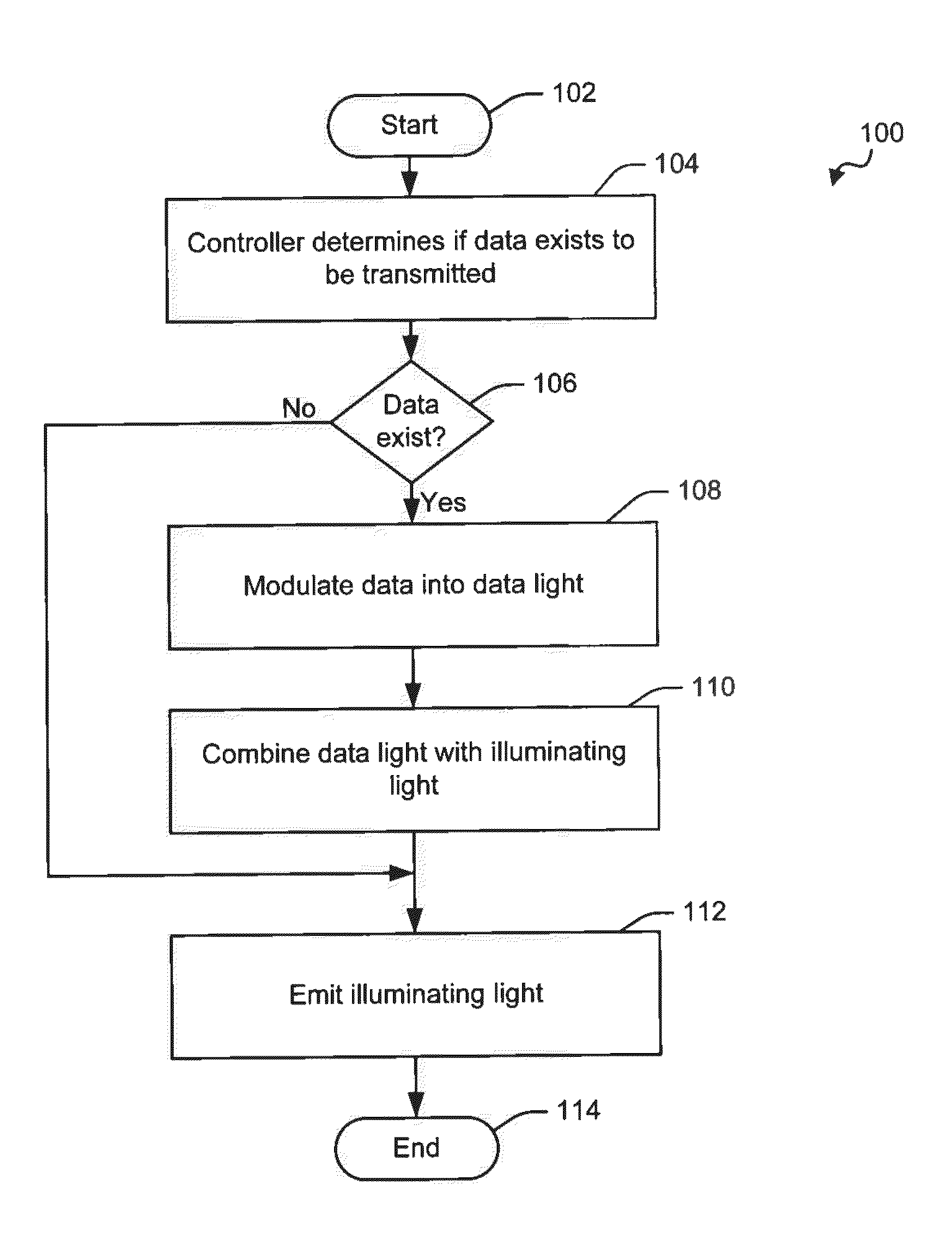
This patent is about a lighting system that can sense and analyze the environment in which it is placed. The system includes nodes that communicate with each other to increase effectiveness. The controller uses machine learning to analyze information and make accurate predictions about the environment. The lighting system is also designed to emit light in a pulsed mode and characterize the luminosity and dominant wavelength of the environment. The technical effects include improved accuracy and efficiency of the lighting system.

Problems solved by technology

Although the incandescent light is capable of illuminating an area, it does so with little efficiency.
However, switches and timers offer little flexibility unless directly engaged by a user.
However, including sensors may increase the number of parts and complexity required to build the lighting system, thereby increasing its manufacturing cost.
Additionally, each lighting device may operate independent of other lighting devices, requiring sensors included in each lighting device, further increasing production costs.
However, the inclusion of wireless radios further increase the complexity and number of components included in the lighting system.
However, the Knapp applications employ data transmission methods that may result in redundant data transmission, decreasing the effective throughput of the system.
Additionally, the Knapp applications lack advanced wavelength sensing functionality, limiting the effectiveness of the system disclosed therein.

Method used


Image

  • Wavelength sensing lighting system and associated methods
  • Wavelength sensing lighting system and associated methods
  • Wavelength sensing lighting system and associated methods

Examples


Embodiment Construction

[0046]The present invention will now be described more fully hereinafter with reference to the accompanying drawings, in which preferred embodiments of the invention are shown. This invention may, however, be embodied in many different forms and should not be construed as limited to the embodiments set forth herein. Rather, these embodiments are provided so that this disclosure will be thorough and complete, and will fully convey the scope of the invention to those skilled in the art. Those of ordinary skill in the art realize that the following descriptions of the embodiments of the present invention are illustrative and are not intended to be limiting in any way. Other embodiments of the present invention will readily suggest themselves to such skilled persons having the benefit of this disclosure. Like numbers refer to like elements throughout.

[0047]In this detailed description of embodiments of the present invention, a person skilled in the art should note that directional terms...


PUM


Abstract

A wavelength sensing lighting system may include a light source, a sensor and a controller. One or more light sources and sensors may be included in an array. The light source may emit an illuminating light and the sensor may sense an environmental light. The illuminating light may include data light. The lighting system may include a plurality of nodes connected in a network. The nodes may communicate by emitting and receiving the data light, which may be analyzed by the controller. The light source and the sensor may be provided by a light emitting semiconductor device that is capable of emitting illuminating light and receiving environmental light. A conversion material may convert the wavelength of a source light into a converted sight.

Description

FIELD OF THE INVENTION[0001]The present invention relates to the field of lighting systems and, more specifically, to lighting systems that can emit and sense light within a wavelength range, and associated methods.BACKGROUND OF THE INVENTION[0002]Lighting systems have been used to illuminate spaces since the invention of fire. Over the years, technology has brought us the incandescent light, which produces light by heating a metal filament, causing it to radiate heat. Although the incandescent light is capable of illuminating an area, it does so with little efficiency.[0003]The fluorescent lamp was introduced to provide comparable light while using less energy. The fluorescent lamp excites a gas, such as mercury vapor, within a confined volume. The atoms of the excited gas typically produce ultraviolet light as it moves between energy levels. The ultraviolet light is then absorbed by a conversion material, such as a phosphor. The phosphor may shift the wavelength range of the absor...

Claims


Application Information

Patent Timeline
Patent Type & Authority Applications(United States)
IPC IPC(8): H05B37/02
CPCH05B33/0869Y02B20/46H05B37/0218H05B45/22H05B47/11Y02B20/40
Inventor MAXIK, FREDRIC S.BRETSCHNEIDER, ERICMEDELIUS, PEDROBARTINE, DAVID E.SOLER, ROBERT R.FLICKINGER, GREGORY
Owner ENVIRONMENTAL LIGHT TECH
Learn More