Heat dissipation structure for electronic device

a technology for electronic devices and heat dissipation structures, which is applied in the direction of cooling/ventilation/heating modifications, semiconductor devices, semiconductor/solid-state device details, etc., can solve the problems of failure and malfunction of devices, and achieve sufficient heat dissipation, improve the reliability of electronic devices, and heat dissipation structure

Inactive Publication Date: 2013-04-11
SHARP KK
View PDF25 Cites 16 Cited by
  • Summary
  • Abstract
  • Description
  • Claims
  • Application Information

AI Technical Summary

Benefits of technology

[0042]According to the present invention, in a heat dissipation structure where an IC chip as a heat generating body is mounted on a board and a heat dissipating sheet is interposed between the IC chip and a cover member, the heat dissipating sheet is pressed against the IC chip via a chip holding portion, and the chip holding portion is an elastic holding portion provided with an elastic section which is elastically deformable and a contact section which makes contact with the heat dissipating sheet. Thus, even when variation occurs in the distance between the IC chip and the cover member, it is possible to bring the IC chip and the heat dissipating sheet, and the heat dissipating sheet and the cover member, into contact with each other under adequate pressure; it is thus possible to obtain a heat dissipation structure for an electronic device that offers sufficient heat dissipation and can improve the reliability of the electronic device.

Problems solved by technology

To cope with miniaturization of electronic devices, electronic components used in them are packed at increasing densities, and arranging electronic components such as IC chips densely in a small space poses a challenge of working out how to deal with the heat generated.
Electronic components such as IC chips mounted on a board, when subjected to a rise in temperature due to the heat they generate during use, may suffer variations in their characteristics, leading to malfunctioning of devices, or may fail themselves.
Inconveniently, however, in a case where different chips have different mounting heights due to their different thicknesses, rubber sheets and heat dissipating plates that suit the different chip heights need to be provided; that is, different heat dissipation structures need to be selected for different IC chips.

Method used


Image

  • Heat dissipation structure for electronic device
  • Heat dissipation structure for electronic device
  • Heat dissipation structure for electronic device

Examples


Embodiment Construction

[0071]Embodiments of the present invention will be described below with reference to the accompanying drawings. The same parts are identified by the same reference signs throughout, and no overlapping description will be repeated unless necessary.

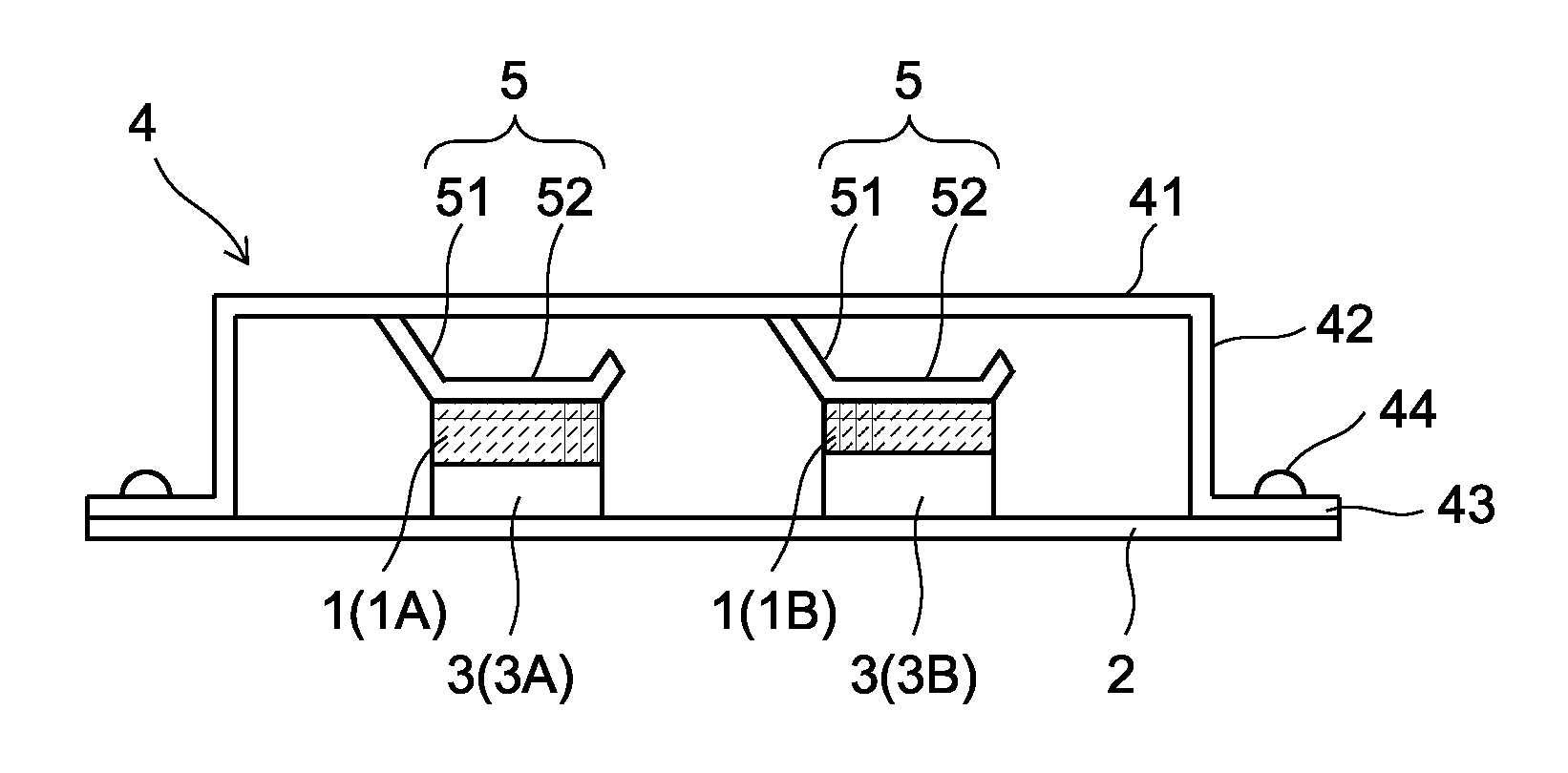
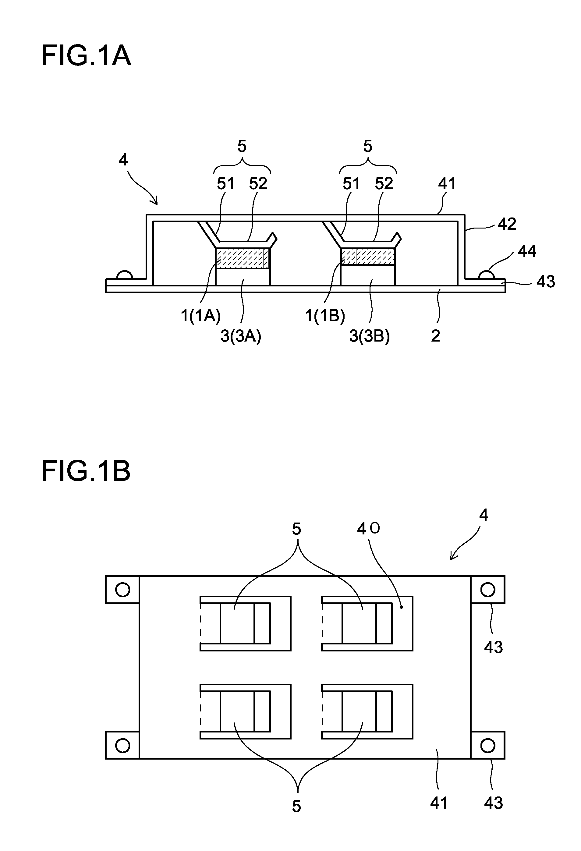
[0072]A heat dissipation structure for an electronic device according to an embodiment of the invention is a heat dissipation structure directed to an electronic device provided with a board on which electronic components, such as IC chips (semiconductor chips), are mounted. It is, for example, a heat dissipation structure as shown in FIG. 1A that achieves heat dissipation by interposing a heat dissipating sheet 1 (1A, 1B) between an IC chip 3 (3A, 3B) mounted on a board 2 and a cover member 4, such as a board cover, covering the mounting face side of the board 2.

[0073]Preferable as this heat dissipating sheet is a rubber sheet that has such flexibility as to be easily deformable in the thickness direction and that has such hardness as to b...


PUM


Abstract

A heat dissipation structure in which an IC chip that generates heat is mounted on a substrate and a heat dissipation sheet is interposed between a cover member and the IC chip to dissipate heat, wherein chip-pressing parts (5) are provided to a cover member (4), so that IC chips (3) are pressed against heat dissipation sheets (1) by the chip-pressing parts (5), and each chip-pressing part (5) is configured from an elastic pressing part equipped with an elastically deformable elastic section (51), and a contact section (52) that comes into contact with a heat dissipation sheet (1), in order to provide an electronic device heat dissipation structure that exhibits sufficient heat dissipation properties and improves the reliability of the electronic device, and has a structure such that it is possible to reliably interpose a heat dissipation sheet between an IC chip and a cover member.

Description

TECHNICAL FIELD[0001]The present invention relates to a heat dissipation structure for an electronic device, for use in liquid crystal display devices and the like.BACKGROUND ART[0002]Recent years have seen proliferation of electronic devices provided with circuit boards on which electronic components such as IC chips (semiconductor chips) are mounted. For example, circuit boards for driving liquid crystal display panels in liquid crystal display devices have many such electronic components mounted on them.[0003]To cope with miniaturization of electronic devices, electronic components used in them are packed at increasing densities, and arranging electronic components such as IC chips densely in a small space poses a challenge of working out how to deal with the heat generated.[0004]Electronic components such as IC chips mounted on a board, when subjected to a rise in temperature due to the heat they generate during use, may suffer variations in their characteristics, leading to mal...

Claims


Application Information

Patent Timeline
Patent Type & Authority Applications(United States)
IPC IPC(8): H01L23/34H01L23/427
CPCH01L23/42H01L23/433H01L23/4338H01L23/34H01L2924/0002H01L23/427H01L2924/00
Inventor KURODA, TATSURO
Owner SHARP KK
Why Eureka
Try Eureka