Control shaft seal

Active Publication Date: 2013-04-11
BORGWARNER INC
View PDF5 Cites 22 Cited by
  • Summary
  • Abstract
  • Description
  • Claims
  • Application Information

AI Technical Summary

Benefits of technology

[0015]The present invention relates to a simplified, low cost, method for keeping an actuator pivot shaft concentric in its bore to enhance the sealing capability thus maximizing the retention of the exhaust gases within the turbocharger and minimizing the escape of said gases to the environment external to the turbocharger and accomplishe

Problems solved by technology

Because a clearance exists between shaft and bearing bore, a flow of hot, toxic exhaust gas through this gap is possible.
This high pressure inside the turbine stage will result in escape of exhaust gas to atmosphere through any apertures or openings.
This soot deposit is unwanted from a cosmetic standpoint, and the escape of said exhaust gas containing CO, CO2, and other toxic chemicals is a health hazard to the occupan

Method used


Image

  • Control shaft seal
  • Control shaft seal
  • Control shaft seal

Examples


first embodiment

[0034]In the invention, as depicted in FIGS. 5A and 5B, in order to cost-effectively constrain the pivot shaft (29) from tilting, while providing an axial thrust constraint, the inventors added a pair of self centering, complementary, mating contact surfaces to the pivot shaft and the bushing, for example, an exterior frusto-conical surface (46) in the bearing (40), and an interior frusto-conical surface (47), to the pivot shaft (29). The surfaces are referred to as “frusto” conical since the peak of the shape would be in the area occupied by the pivot shaft, and thus, would be “cut off”. This frusto-conical interface prevents the pivot shaft from rocking and tilting on the bushing while centering the shaft in the bearing. One net effect of the frusto-conical interface is that the seal ring no longer must endure tilting of the relative alignment between the sides of the seal ring to the cheeks of the seal ring groove and also to any relative tilting between the outer diameter of the...

second embodiment

[0035]In the invention, as depicted in FIGS. 6A and 6B, in order to cost-effectively constrain the pivot shaft (29) from tilting, while providing an axial thrust constraint, the inventors added a pair of self centering, complementary, mating contact surfaces to the pivot shaft and the bearing, for example, an exterior frusto-spherical surface (48) in the bearing (40) and an interior frusto-spherical surface (47) to the pivot shaft (29). The surfaces are referred to as “frusto” spherical since the peak of the shape would be in the area occupied by the pivot shaft, and thus, would be “cut off”. This frusto-spherical interface prevents the pivot shaft from rocking and tilting on the bearing while centering the shaft in the bushing. One net effect of the frusto-spherical interface is that the piston ring no longer must endure tilting of the relative positions of the cheeks of the seal ring to the sides of the seal ring groove and also to any relative tilting between the outer diameter o...

third embodiment

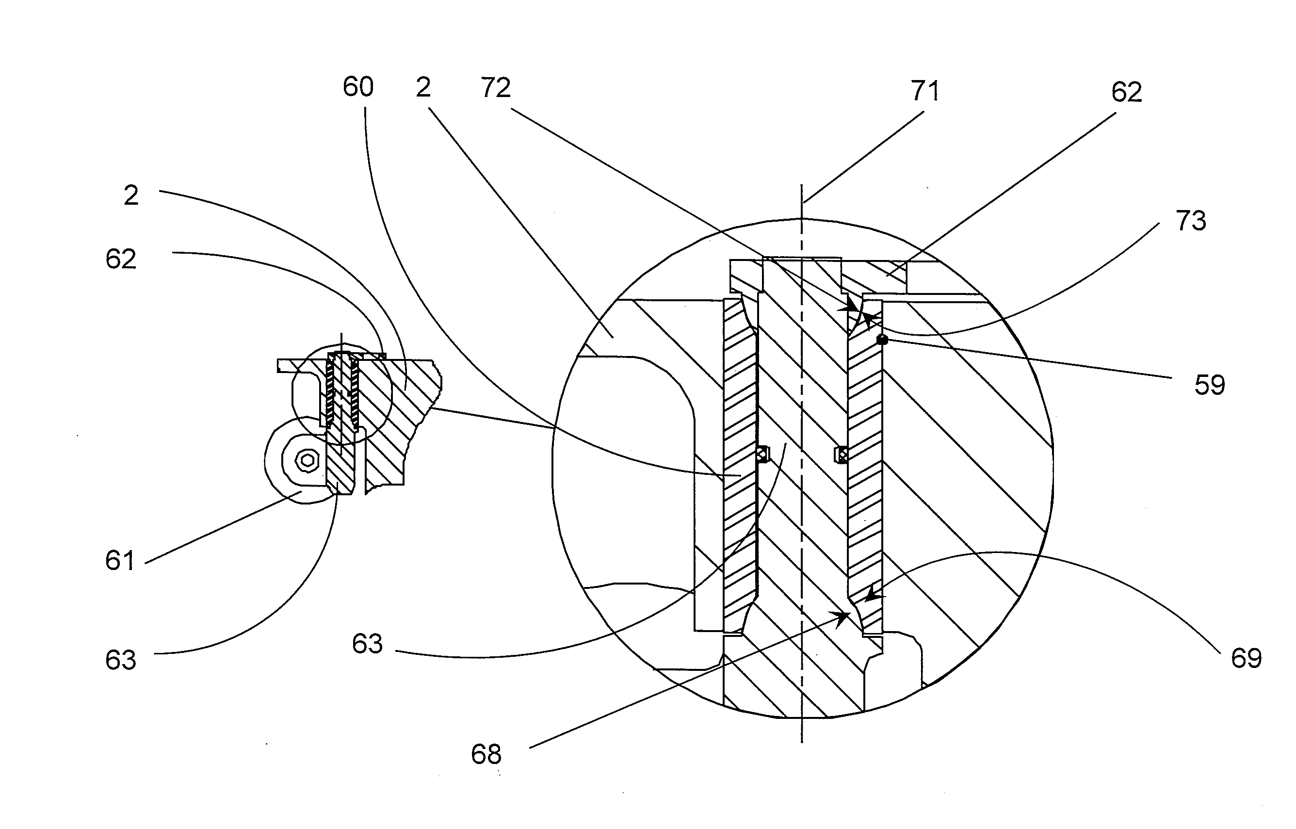
[0041]In the invention, as depicted in FIGS. 8A, 8B, the inventors added a pair of self centering, complementary, mating contact surfaces to the pivot shaft and the bearing, for example, an exterior frusto-spherical surface (69) in the bearing (60) and an interior frusto-spherical surface (68) to the wastegate pivot shaft (63). The surfaces are referred to as “frusto” spherical since the peak of the shape would be in the area occupied by the pivot shaft, thus, would be “cut off”. This frusto-spherical interface prevents the pivot shaft from rocking and tilting on the bearing while centering the shaft in the bushing. One net effect of the frusto-spherical interface is that the piston ring no longer must endure tilting of the relative positions of the cheeks of the seal ring to the sides of the seal ring groove and in addition any relative tilting between the outer diameter of the seal ring and the inner diameter of its mating bore in the bearing. Another net effect of the frusto-sphe...


PUM


Abstract

The propensity for gas leakage around a shaft, which connects volumes of differing pressures, in, e.g., a turbocharger is minimized in a simple cost-effective manner. The addition of a complementary pair of frusto-spherical, conical, or other profiles to the interface of the shaft and its bearing maintain concentricity of the shaft in its bore and thus improve the efficacy of existing sealing protocols.

Description

FIELD OF THE INVENTION[0001]This invention addresses the need for an improved shaft sealing design for turbocharger shafts which pass through the walls of the housing castings.BACKGROUND OF THE INVENTION[0002]Turbochargers are a type of forced induction system. They deliver air, at greater density than would be possible in the normally aspirated configuration, to the engine intake, allowing more fuel to be combusted, thus boosting the engine's horsepower without significantly increasing engine weight. A smaller turbocharged engine, replacing a normally aspirated engine of a larger physical size, will reduce the mass and aerodynamic frontal area of the vehicle.[0003]Turbochargers use the exhaust flow from the engine exhaust manifold to drive a turbine wheel, which is located in the turbine housing. Once the exhaust gas has passed through the turbine wheel and the turbine wheel has extracted energy from the exhaust gas, the spent exhaust gas exits the turbine housing through the exduc...

Claims


Application Information

Patent Timeline
IPC IPC(8): F04D27/00F04D29/10
CPCF01D17/165F02B37/186F02B37/24F04D27/0246Y02T10/144F04D27/002F04D29/102F02B39/00Y02T10/12F01D11/00F01D17/16
Inventor WARD, DANIEL N.
Owner BORGWARNER INC
Why Eureka
Try Eureka